Method for inspecting magnetic characteristics of a plurality of thin magnetic heads by means of local application of magnetic field

a thin-film magnetic head and local application technology, applied in the direction of magnetic measurement, instruments, measurement devices, etc., can solve the problems of limiting the frequency of an alternating magnetic field, affecting the efficiency of inspection, and difficult to achieve frequencies higher than 1 megahertz, etc., to achieve the effect of simulation of a high-frequency alternating magnetic field

Inactive Publication Date: 2009-09-03
TDK CORPARATION
View PDF1 Cites 12 Cited by
  • Summary
  • Abstract
  • Description
  • Claims
  • Application Information

AI Technical Summary

Benefits of technology

[0008]An object of the present invention is to provide a method for inspecting magnetic characteristics of thin film magnetic heads in an efficient manner, the method being capable of sufficiently simulating a high-frequency alternating magnetic field. Another object of the present invention is to provide a magnetic field applying bar which can be suitably used in the method for inspecting the magnetic characteristics of thin film magnetic heads.

Problems solved by technology

This method enables sliders to be inspected in the same environment as in a state in which the sliders are actually mounted on hard disk drives, but is disadvantageous as regards the efficiency of the inspection.
However, in a conventional Helmholtz coil, there is a limitation to an increase in the frequency of an alternating magnetic field because of the characteristics of the device.
Frequencies in the order of several hundred kilohertz are within the capability of the Helmholtz coil, but frequencies higher than 1 megahertz are difficult to achieve.
Thus, it has already been difficult to completely simulate the actual environment by a conventional QST.
Use of a spin stand may realize such high frequencies, but will lead to inefficiency in the inspection.

Method used


Image

  • Method for inspecting magnetic characteristics of a plurality of thin magnetic heads by means of local application of magnetic field
  • Method for inspecting magnetic characteristics of a plurality of thin magnetic heads by means of local application of magnetic field
  • Method for inspecting magnetic characteristics of a plurality of thin magnetic heads by means of local application of magnetic field

Examples


Embodiment Construction

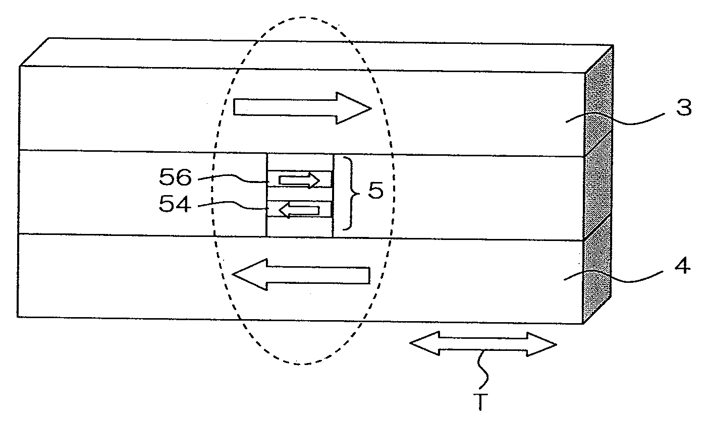
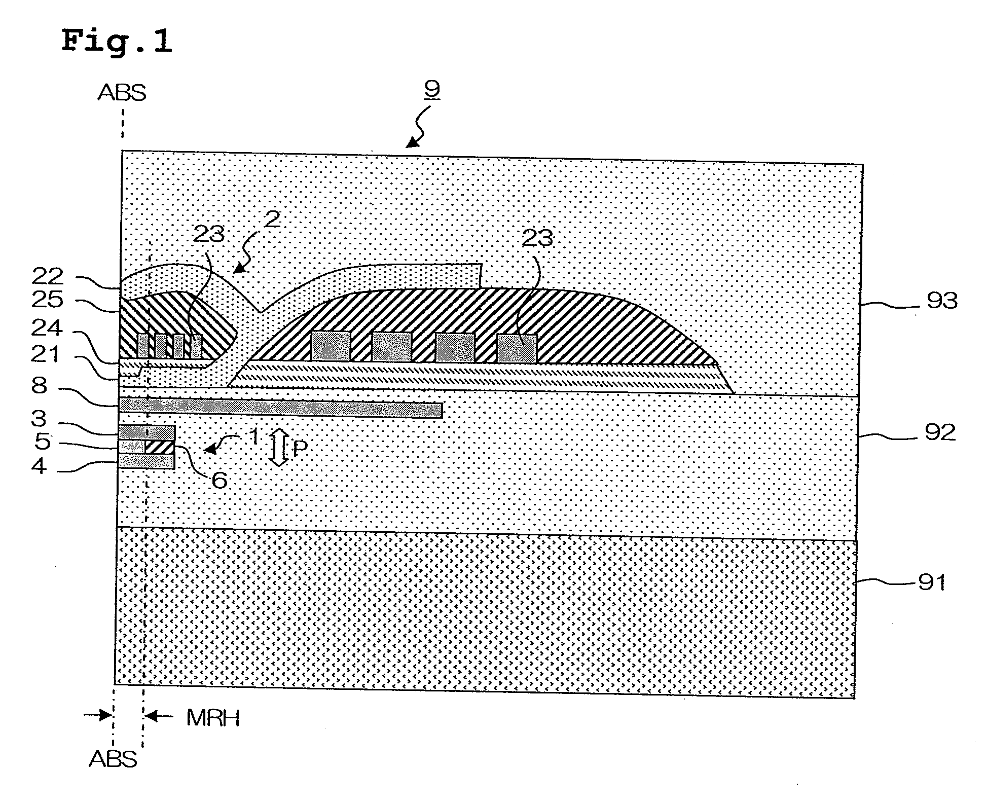
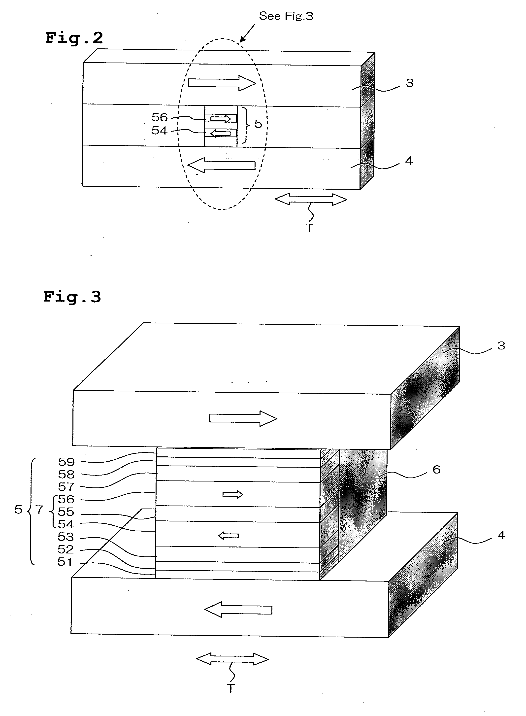
[0028]First, a description will be made of a general outline of a thin film magnetic head to which the present invention is applied. The present invention is applicable to a thin film magnetic head that is provided with any element that utilizes the magnetoresistance effect. Examples of these elements include a CIP (Current in Plane)-GMR element in which a sense current flows in parallel with the film plane thereof, a CPP (Current Perpendicular to the Plane)-GMR element and a TMR (Tunnel Magneto-resistance) element in both of which a sense current flows perpendicularly to the film plane thereof. An example of a thin film magnetic head that is particularly suitable for the present invention will be described. In the magnetoresistance effect element of a thin film magnetic head, the function of a magnetic field sensor is achieved by a pair of magnetic layers, which are stacked in the vertical direction and whose magnetization directions change according to an external magnetic field, ...


PUM


Abstract

A method for inspecting magnetic characteristics of a thin film magnetic head that is arranged in a row bar includes: a step of preparing a row bar having sliders including a thin film magnetic head formed therein and lapping guides having magnetoresistance effect; a step of preparing a magnetic field applying row bar having first and second magnetic field applying elements; a first positioning step in which said magnetic field applying row bar is arranged opposite to said row bar; a second positioning step in which a relative movement between said magnetic field applying row bar and said row bar is made so that at least one of said lapping guides exhibits a largest output voltage; and a measurement step in which a relationship between the intensity of the magnetic field and an output voltage of a magnetic field sensor is obtained.

Description

BACKGROUND OF THE INVENTION[0001]1. Field of the Invention[0002]The present invention relates to a method for inspecting magnetic characteristics of thin film magnetic heads, more particularly, to a method for inspecting thin film magnetic heads arranged in a row bar.[0003]2. Description of the Related Art[0004]Conventionally, thin film magnetic heads are manufactured by the following steps. First, a stack that includes a magnetic field sensor (a read head portion) and a write head portion is formed on a substrate in the wafer process. Next, the wafer is diced and separated into row bars. A plurality of sliders is disposed in each row bar along the longitudinal direction thereof, and each slider is provided with a thin film magnetic head that is formed in the wafer process. A row bar serves as a work unit in a lapping step for forming an air bearing surface. When lapping is completed, the row bar is separated into individual sliders, each of which is then assembled into a head gimba...

Claims


Application Information

Patent Timeline
Patent Type & Authority Applications(United States)
IPC IPC(8): G01R33/12
CPCG01R33/1207
Inventor SHIMAZAWA, KOJI
Owner TDK CORPARATION
Why Eureka
Try Eureka