
Single-Piece Propeller And Method Of Making

Active Publication Date: 2009-09-03
TEXTRON INNOVATIONS
View PDF13 Cites 33 Cited by
  • Summary
  • Abstract
  • Description
  • Claims
  • Application Information

AI Technical Summary

Problems solved by technology

The solid carbon fiber cores are relatively heavy, but are necessary to carry the structural loads during propeller operation, because the composites skins alone are incapable of doing so.

Method used


Image

  • Single-Piece Propeller And Method Of Making
  • Single-Piece Propeller And Method Of Making
  • Single-Piece Propeller And Method Of Making

Examples


Embodiment Construction

[0015]Embodiments of the present disclosures provide a fixed-pitch propeller and method of manufacturing the same.

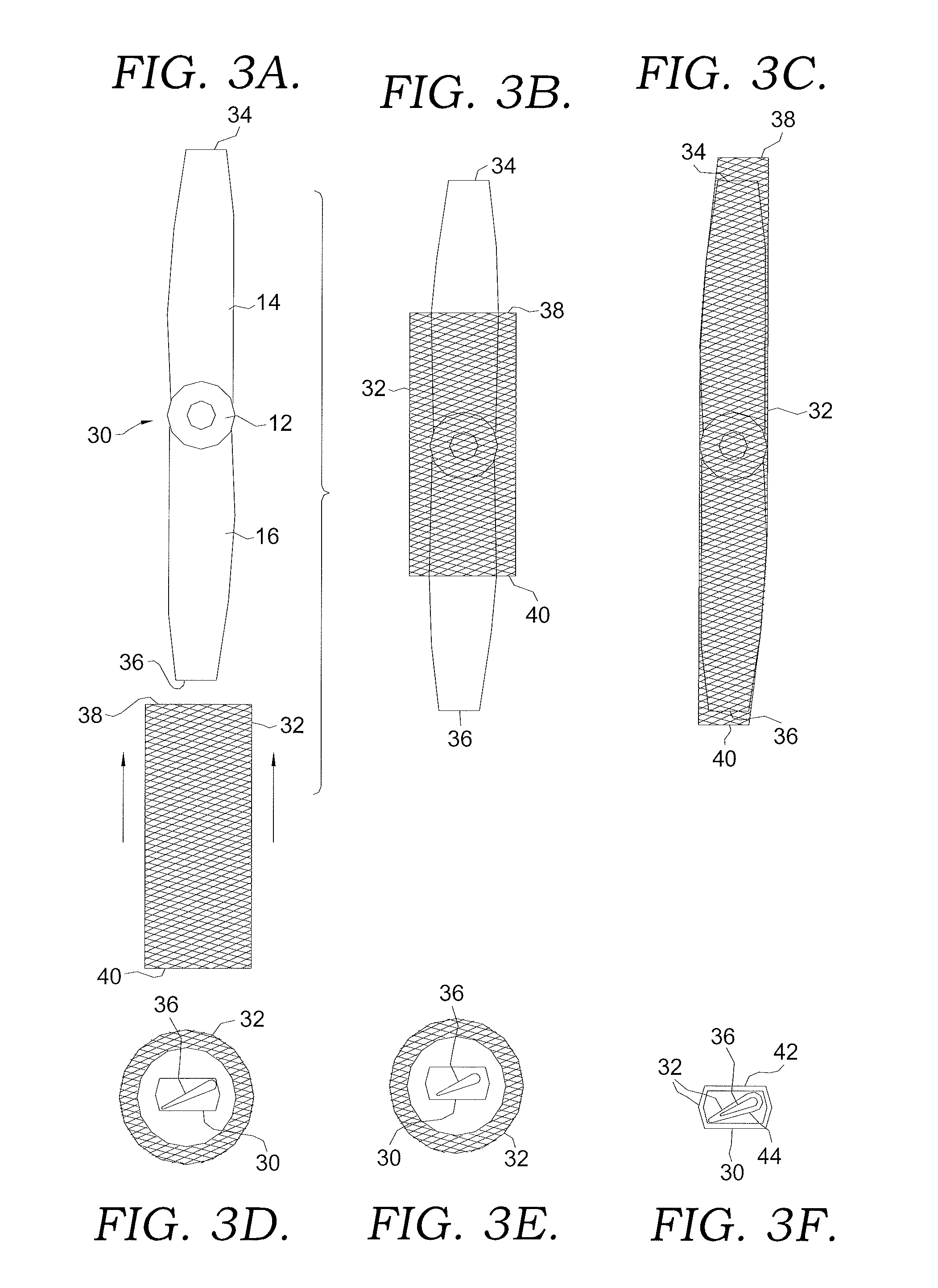
[0016]Because the disclosed single-piece propeller is manufactured using lightweight foam cores and is constructed of extremely strong and durable composite materials, its weight is roughly half that of the conventional Aluminum single-piece propellers now used. Further, the single-piece end product is easily bolted onto the front drive mechanisms of the aircraft using a crush plate. Finally, because it is of seamless composite construction, the propeller is largely maintenance and labor free.

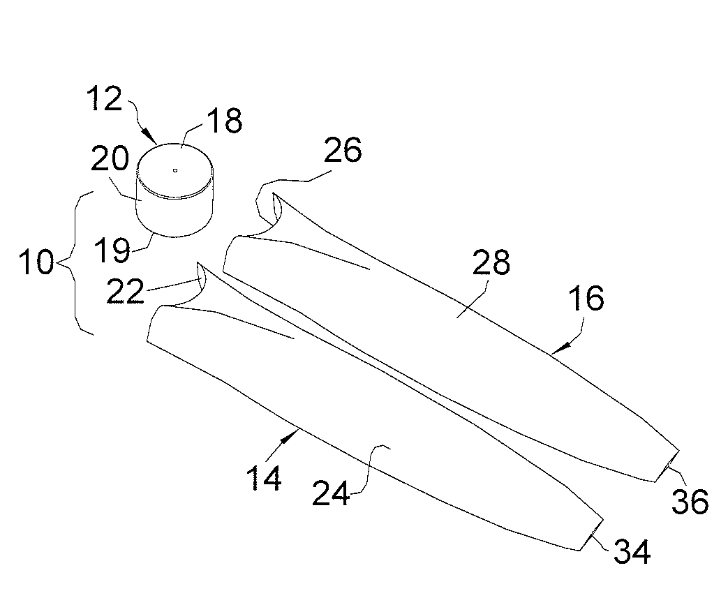
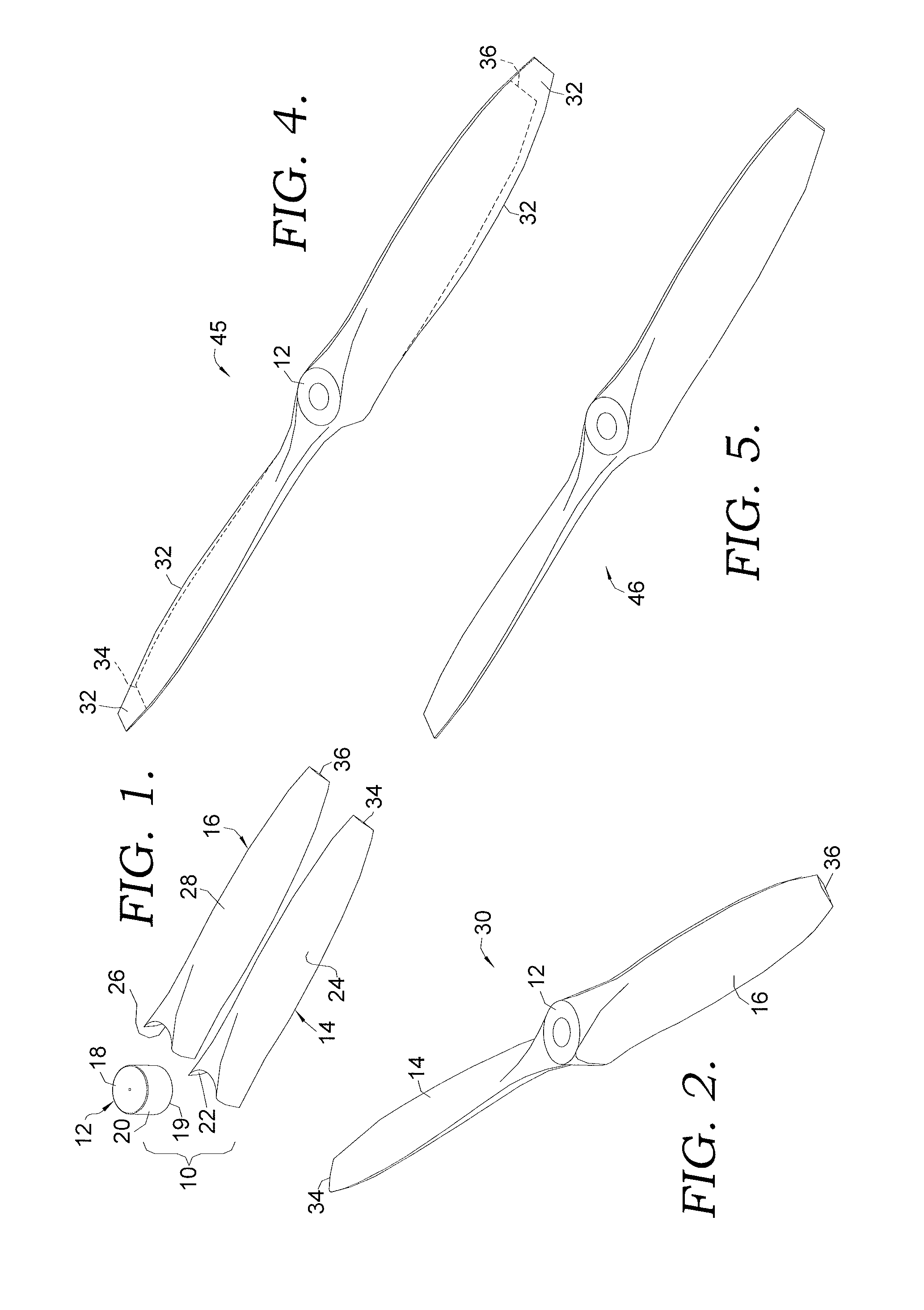
[0017]The single-piece blade, in one embodiment, is manufactured according to the following process. First, the core components are provided. These components, as they appear before assembly, can be seen in FIG. 1. Referring to the figure, it can be seen that a grouping of parts 10 includes a hub core 12, a first blade core half 14, and a second blade core half 16.

[0018]Hub core 12,...


PUM

PropertyMeasurementUnit
compressive forcesaaaaaaaaaa
core structureaaaaaaaaaa
poweraaaaaaaaaa

Abstract

A method for making a propeller product is disclosed. The propeller is formed using polyurethane cores adhered to a laminate hub to form a core assembly. An encapsulating structural laminate skin is then formed on the core assembly using a resin-transfer-molding process to create a single-piece composite propeller.

Description

CROSS-REFERENCE TO RELATED APPLICATIONS[0001]None.BACKGROUND OF THE INVENTION[0002]1. Field of the Invention[0003]The disclosed embodiments relate generally to the field of aeronautics. More specifically, the invention relates to the technologies of propeller manufacture and design.[0004]2. Description of the Related Art[0005]Propellers transmit power by converting rotational motion into thrust. This thrust is used to propel a vehicle, e.g., an aircraft, ship, or submarine through a fluid. Some propellers have a fixed pitch—in other words, the angle of the blades do not change as the aircraft is in operation. Other propellers blades change angle to accommodate different operating speeds of the aircraft. These are known as variable-pitch blades.[0006]One conventional design for a fixed-pitch propeller is made of solid, single piece of Aluminum. For this kind of blade, the entire apparatus is produced as an integral piece of material. Another fixed-pitch design is constructed of a sin...

Claims


Application Information

Patent Timeline
Patent Type & Authority Applications(United States)
IPC IPC(8): B64C11/20
CPCB64C11/26Y10T156/1057Y10T29/49332Y10T156/1089B64U20/65B64U10/00B64C11/00B64C11/02B64C11/04B64C11/20B32B37/00B32B27/00B32B27/38B32B9/00B32B37/02B32B37/18
Inventor BALL, DANNYPFEIFFER, KEVIN
Owner TEXTRON INNOVATIONS
Learn More