Vital signs monitoring using personal protective equipment

Inactive Publication Date: 2009-09-03
RYAN RICHARD H
View PDF42 Cites 49 Cited by
  • Summary
  • Abstract
  • Description
  • Claims
  • Application Information

AI Technical Summary

Benefits of technology

[0013]In accordance with another aspect of the present invention, the vital signs data signals from the vital signs monitoring system and PPE are received at a location remote from the person being monitored (e.g., on a sideline of the competition field of the athletic event). Those received signals may be received by a gateway to a network, such as the Internet, and transmitted to a

Problems solved by technology

Participation in athletic activities can expose the participants to physical harm.
Collisions between participants frequently occur in certain sports (e.g., football, field hockey, lacrosse, ice hockey, and the like) which can cause physical harm and as a result, personal protective equipment (“PPE”) has been developed.
Consequently, there is space between the wearer's head and the outer shell.
Injury to athletes can also occur when competition for prolonged periods in an abnormally high temperature environment is conducted.
Football, lacrosse, and other sports may require high levels of exertion from the athletes for substantial time periods in elevated temperatures.
Such exertion levels coupled with high temperatures also have the potential to injure a person.
Individuals such as steel mill and power plant workers and heavy machine operators perform duties in such environments and can be exposed to considerable risk of illness and/or injury due to heat stress.
These particular environments can inv

Method used


Image

  • Vital signs monitoring using personal protective equipment
  • Vital signs monitoring using personal protective equipment
  • Vital signs monitoring using personal protective equipment

Examples


Embodiment Construction

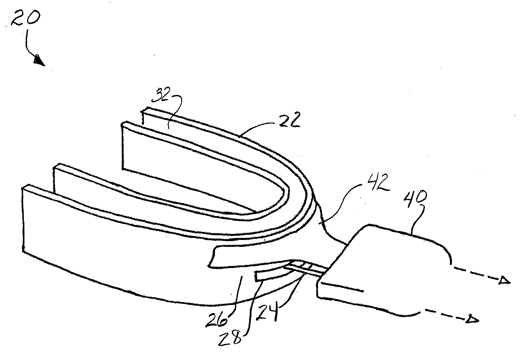
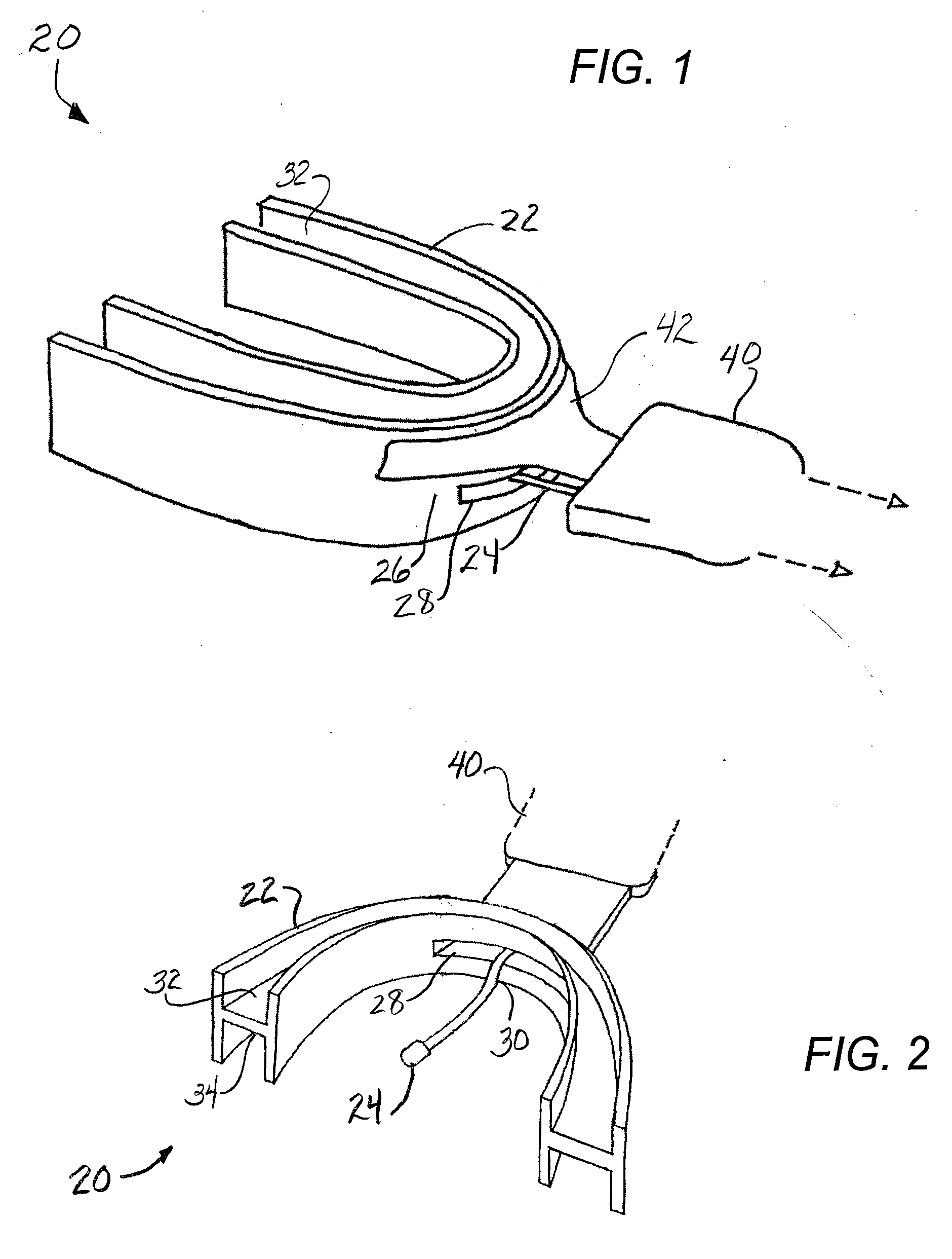
[0032]Referring now in more detail to the exemplary drawings for purposes of illustrating embodiments of the invention, wherein like reference numerals designate corresponding or like elements among the several views, there is shown in FIGS. 1 and 2 a vital signs monitoring system 20 mounted in personal protective equipment (PPE), in this case a mouth guard 22. In this embodiment, a thermal sensor 24 is positioned through an aperture 28 the front edge 26 of the mouth guard. The thermal sensor is curved 30 downward so that it will be positioned under the wearer's tongue when the mouth guard is in place. This will cause the thermal probe to come into contact with the internal oral tissue of the wearer to provide temperature data about the oral cavity of the person wearing the mouth guard. In this case the mouth guard 22 has been formed with an upper channel 32 and a lower channel 34 to accept both the wearer's upper row of teeth and lower row of teeth, respectively.

[0033]The mouth gua...


PUM


Abstract

A vital signs monitor system is integrated with personal protective equipment (“PPE”) so that upon wearing the PPE, the monitor is placed in an operational position to monitor a vital sign. In one embodiment, the vital signs sensor comprises a thermal sensor located at a mouth guard to automatically make operational contact with tissue under the tongue when the mouth guard is worn. A second vital signs monitor comprising reflective pulse oximetry devices senses oxygen saturation and heart rate. Vital signs data are communicated to an RF module located in an associated helmet for transmission to a remote location. A gateway at that remote location receives the transmitted vital signs data and forwards that data to a data collection, organization, and access system that is programmed to make the vital signs data available over the Internet. Medical personnel, coaches, supervisors at the location of the PPE can monitor the vital signs of the wearer by accessing the data collection, organization, and access system with hand held, or portable computing equipment over the Internet.

Description

CROSS-REFERENCES TO RELATED APPLICATIONS[0001]This application claims the benefit under 35 U.S.C. §119(e) of U.S. Provisional Application No. 61 / 032,895 filed Feb. 29, 2008, which is incorporated herein by reference in its entirety.[0002]The present invention relates generally to monitoring vital signs of a person, and more particularly, to incorporating vital signs sensing into personal protective equipment.BACKGROUND[0003]Participation in athletic activities can expose the participants to physical harm. Collisions between participants frequently occur in certain sports (e.g., football, field hockey, lacrosse, ice hockey, and the like) which can cause physical harm and as a result, personal protective equipment (“PPE”) has been developed. Mouth guards are coverings worn over the teeth to protect against concussion during participation in sports, and in doing so, the teeth also receive protection. The use of mouth guards is well known. Additionally, the use of helmets in a variety o...

Claims


Application Information

Patent Timeline
IPC IPC(8): A61B5/00G16H40/67
CPCA61B5/0002A61B5/01A63B2071/088A63B2230/50A63B2230/20A61B5/145A61B5/682A63B71/085A61B5/02A61B5/0008G06F19/3418A63B2230/04A63B2230/08Y10S128/903G16H40/67
Inventor RYAN, RICHARD H.
Owner RYAN RICHARD H
Why Eureka
Try Eureka