Hand Held Massaging Tool

a technology of hand held and massage tool, which is applied in vibration massage, mechanical energy handling, propulsion systems, etc., can solve the problems of not having the ability to dynamically change the intensity or amplitud

Active Publication Date: 2009-09-03
MERLEX CORP PTY LTD
View PDF64 Cites 16 Cited by
  • Summary
  • Abstract
  • Description
  • Claims
  • Application Information

AI Technical Summary

Problems solved by technology

Some forms of the prior art massagers have controls to vary the motor speed which provides variation in vibration through the centrifugal effects in counterweight versions but do not have the capacity to dynamically change the amplitude or intensity of stimulation at a predetermined frequency.

Method used


Image

  • Hand Held Massaging Tool
  • Hand Held Massaging Tool
  • Hand Held Massaging Tool

Examples


Embodiment Construction

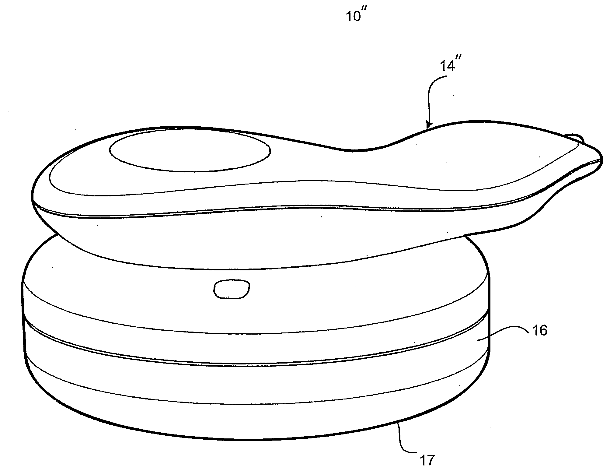
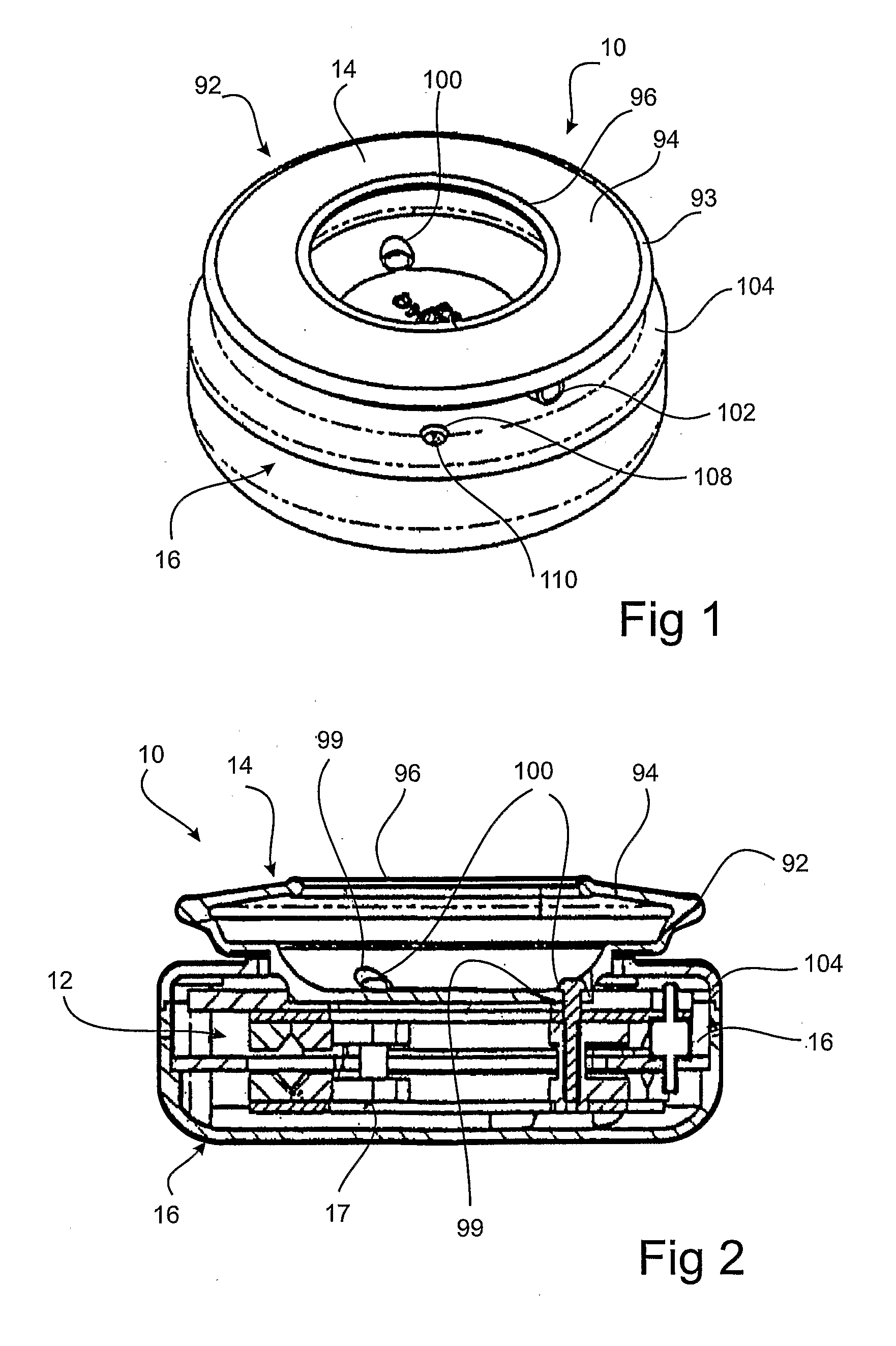
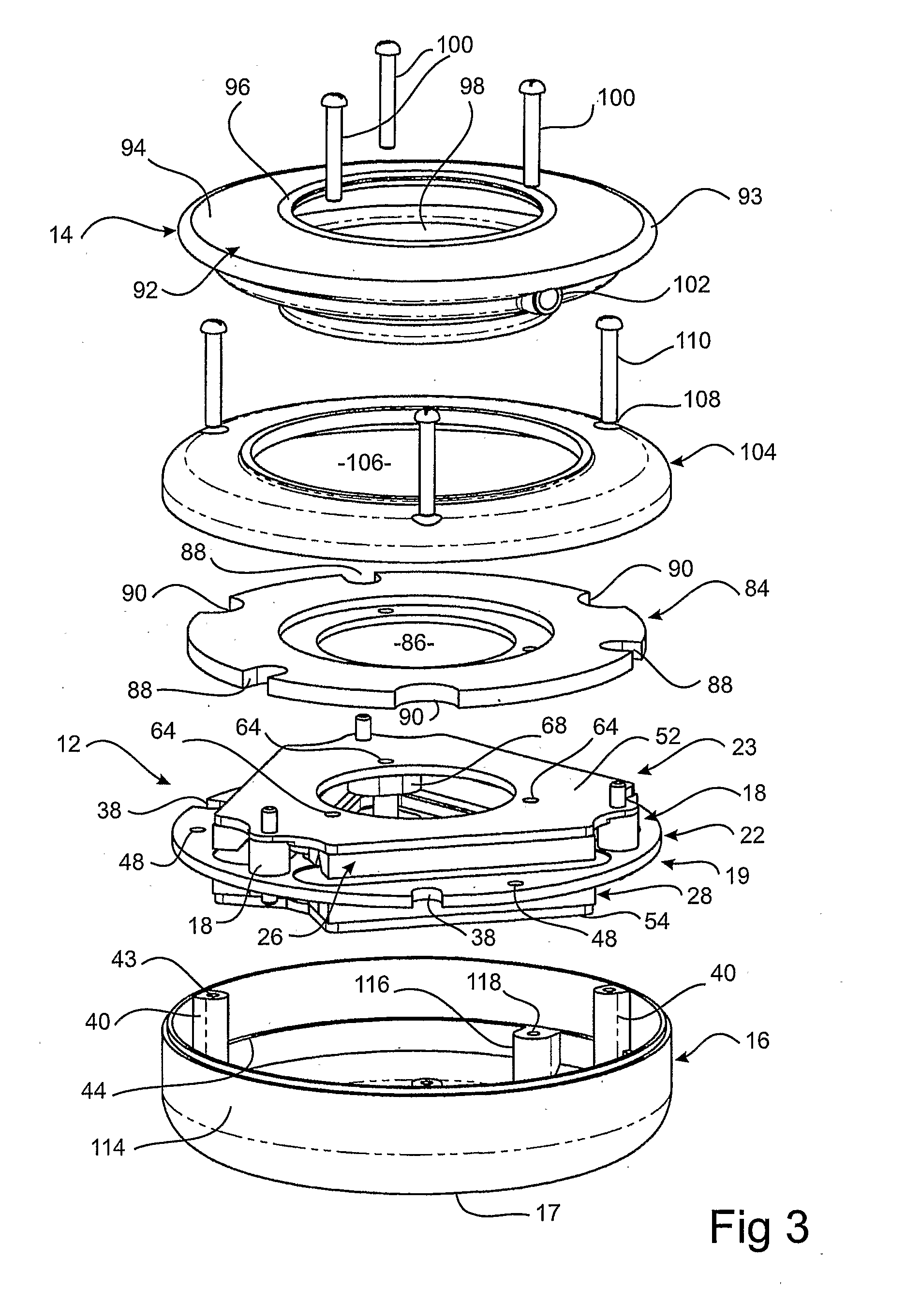
[0035]With reference to the accompanying drawings and in particular FIGS. 1 to 4, an embodiment of the hand held tool 10 comprises an electric motor 12, a handle 14, a contact member 16, and a resilient coupling 18 coupled between the handle 14 and the contact member 16.

[0036]The contact member 16 has a contact surface portion 11 that lies in a first plane. With particular reference to FIG. 4, the electric motor 12 comprises an armature 19, having a plurality of electric current carrying coils 20a, 20b and 20c (hereinafter referred to in general as “coils 20”) supported by a carrier 22, and a stator 23 which comprises a magnet 24 producing lines of magnetic flux travelling in a direction substantially perpendicular to a direction of current flowing through the coils 20 so as to produce a plurality of transverse linear (i.e. translational) forces F. Each coil is composed of two windings: coil 20a comprising windings 20a1 and 20a2, coil 20b comprising windings 20b1 and 20b2 and coil 2...


PUM


Abstract

A hand held tool (10) comprises a handle (14), a contact member (16), and an electric motor (12). The contact member has a contact surface portion 17 that lies in the first plane. The motor (12) has a stator (23) and an armature (19) where the armature (19) is able to move with non-rotary translational motion in a second plane relative to the stator (23), the second plane being parallel to the first plane. One of the stator (23) and the armature (19) is attached to the handle (14), while the other is attached to the contact member (16). Therefore, relative motion of the stator (23) and armature (19) is translated to relative motion between the handle (14) and the contact member (16). A resilient coupling (18) is coupled between the handle 14 and the contact member (16) and applies a bias against the relative motion between the handle (14) and contact member (16).

Description

FIELD OF THE INVENTION[0001]The present invention relates to a hand held tool, and more particularly to a hand held massage tool or like device for personal use on the body, such as a face cleanser, skin rejuvenator, cellulite treatment, subcutaneous and epifascial tissue manipulation, muscle rejuvenation, body fluid circulatory aid, pain management etc.BACKGROUND OF THE INVENTION[0002]Hand held electrically driven massagers have been available in many different forms for a long period of time. Generally, such massagers rely on percussion or impact in order to generate vibrations that are applied to the body. This is achieved using an electric motor having a stator and a rotor where the rotor rotates about a central axis. The rotor in turn rotates an eccentrically weighted disc or eccentrically disposed weights to generate vibration or operates through an offset crank arrangement to provide the stimulation.[0003]Some forms of the prior art massagers have controls to vary the motor s...

Claims


Application Information

Patent Timeline
Patent Type & Authority Applications(United States)
IPC IPC(8): A61H7/00
CPCA61H7/004A61H23/0218A61H23/0263A61H2201/0153A61H2201/0157H02K7/06A61H2201/1666A61H2205/022A61H2207/00H02K41/031H02K2201/18A61H2201/1604
Inventor HOBSON, BARRY REGINALDPAOLIELLO, ANGELO
Owner MERLEX CORP PTY LTD
Why Eureka
Try Eureka