Two phase exhaust for internal combustion engine

a technology of internal combustion engine and two-phase exhaust, which is applied in the direction of machines/engines, output power, transportation and packaging, etc., can solve the problems of system not providing a system having a maximum efficiency, reducing the efficiency of the engine, and reducing the otherwise outstanding efficiency of such an engine typ

Active Publication Date: 2009-09-10
DEERE & CO
View PDF8 Cites 56 Cited by
  • Summary
  • Abstract
  • Description
  • Claims
  • Application Information

AI Technical Summary

Problems solved by technology

The usual steps for combustion management to minimize emissions typically decrease efficiency of the engine.
In the case of the compression ignition or diesel engine cycle, the need to reduce oxides of nitrogen requires significant alteration to the operating cond

Method used


Image

  • Two phase exhaust for internal combustion engine
  • Two phase exhaust for internal combustion engine

Examples


Embodiment Construction

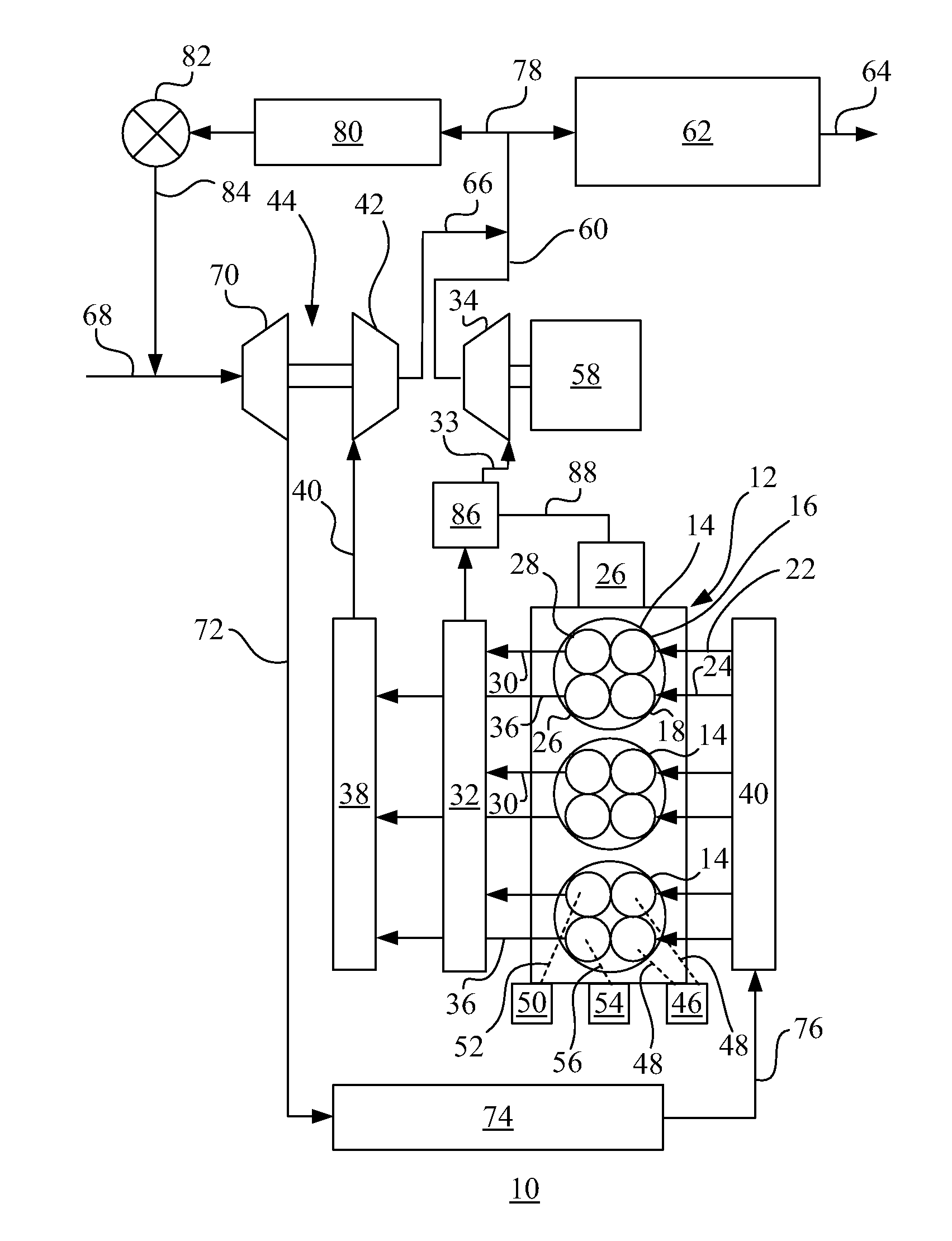
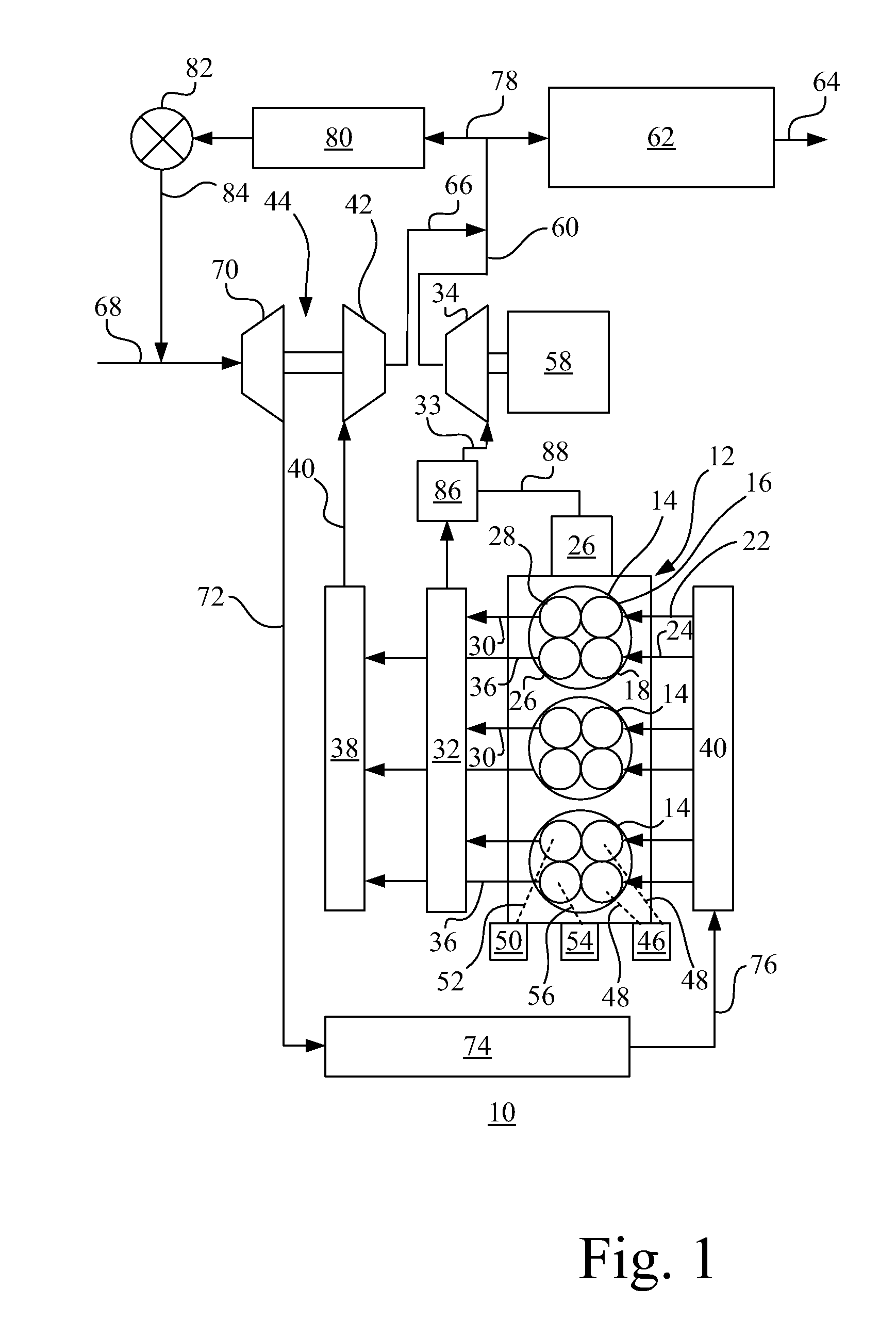
[0011]FIG. 1 shows a prime mover system 10 having an internal combustion engine 12 with multiple cylinders in which pistons (not shown) reciprocate to provide variable volume combustion chambers 14. Although the engine shows three cylinders, it should be apparent to those skilled in the art that a great variety in the number of cylinders may be employed, according to the size and to the duty cycle required of the engine 12. The combustion chamber 14 has at least one intake valve 16 and preferably an additional intake valve 18 for admitting combustion air from an intake manifold 20 passed via passages 22 and 24. The air thus introduced into combustion chamber 14 goes through a cycle including an intake portion, compression portion, expansion portion and exhaust portion. The air that has been pressurized is combined with fuel from a fuel system 26 and ignited to combust and drive the expansion portion of the cycle to generate power.

[0012]The combustion process may be a spark ignition ...


PUM


Abstract

An internal combustion engine having a reciprocating multi cylinder internal combustion engine with multiple valves. At least a pair of exhaust valves are provided and each supply a separate power extraction device. The first exhaust valves connect to a power turbine used to provide additional power to the engine either mechanically or electrically. The flow path from these exhaust valves is smaller in area and volume than a second flow path which is used to deliver products of combustion to a turbocharger turbine. The timing of the exhaust valve events is controlled to produce a higher grade of energy to the power turbine and enhance the ability to extract power from the combustion process.

Description

[0001]This invention was made with Government support under contract DE-FC26-05NT42422 awarded by the Department of Energy. The United States Government has certain rights in this invention.FIELD OF THE INVENTION[0002]The present invention relates to internal combustion engines and more specifically to prime mover systems incorporating internal combustion engines and power extraction devices.BACKGROUND OF THE INVENTION[0003]For over a hundred years, piston engines have been utilized to convert the energy in hydrocarbon based fuel to useful power outputs. Typically, these engines have incorporated variable volume combustion chamber or chambers using a cycle having an intake portion, a compression portion, an expansion portion and an exhaust portion. The variable volume combustion chamber is most typically defined by a reciprocating piston in a cylinder bore and connected by appropriate mechanical devices to a crankshaft or other rotary output component. The engines may be two cycle o...

Claims


Application Information

Patent Timeline
IPC IPC(8): F02D23/00F02B33/44F01N13/10
CPCF02D13/0249F02D13/0257F01L2800/06F01N5/04F01N13/107Y02T10/18F02B39/00F02B41/10Y02T10/144Y02T10/16Y02T10/163F02B37/20Y02T10/12
Inventor VUK, CARL T.
Owner DEERE & CO
Why Eureka
Try Eureka