Combustion cap with crown mixing holes

a technology of combustion cap and mixing hole, which is applied in the direction of machines/engines, mechanical equipment, lighting and heating apparatus, etc., can solve the problem of low nox level

Inactive Publication Date: 2009-09-10
GENERAL ELECTRIC CO
View PDF18 Cites 98 Cited by
  • Summary
  • Abstract
  • Description
  • Claims
  • Application Information

AI Technical Summary

Problems solved by technology

In this way, the multiple dedicated premixing sections or tubes allow thorough premixing of fuel and air prior to burning, which ultimately results in low NOx levels.

Method used


Image

  • Combustion cap with crown mixing holes
  • Combustion cap with crown mixing holes
  • Combustion cap with crown mixing holes

Examples


Embodiment Construction

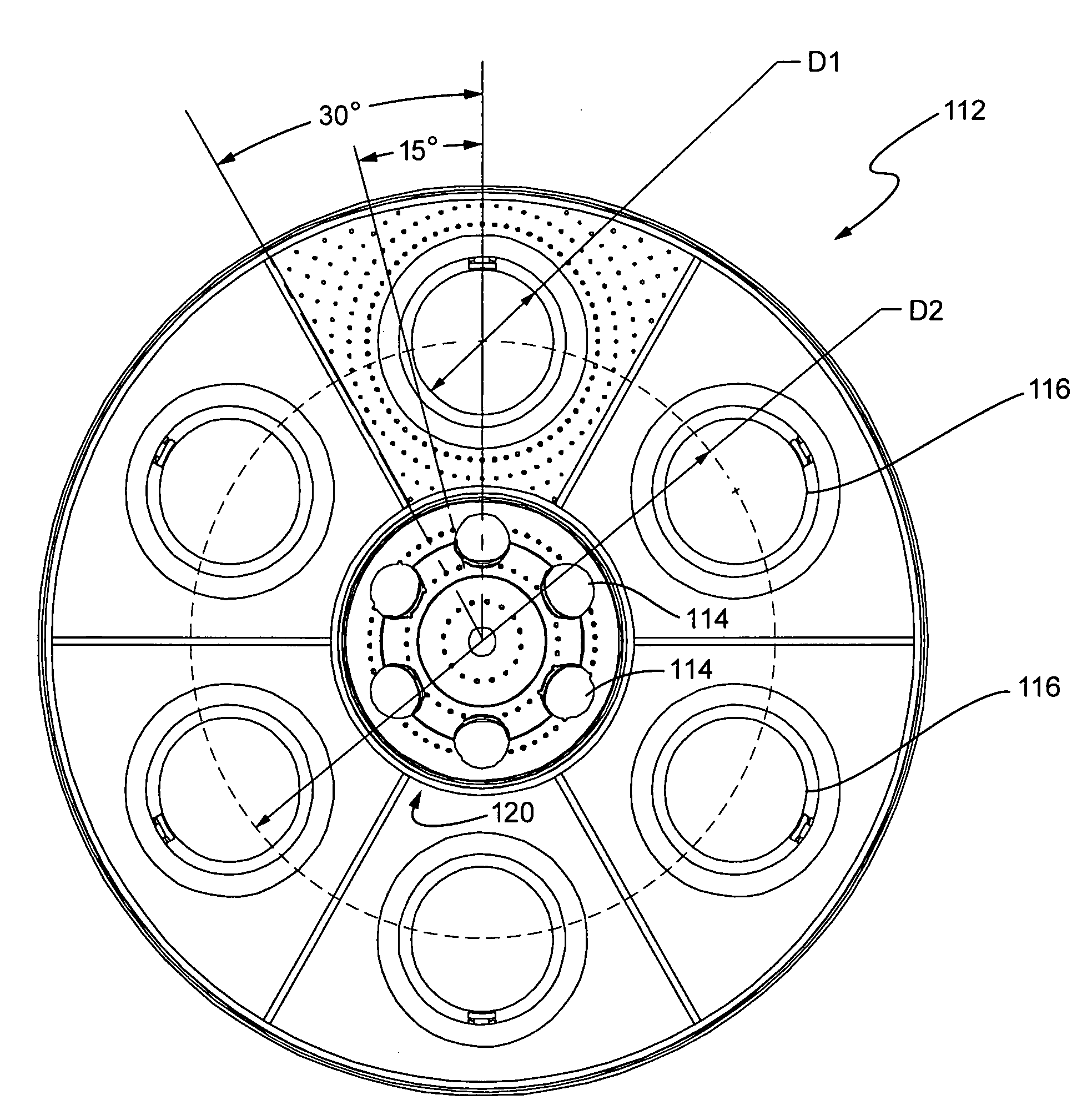
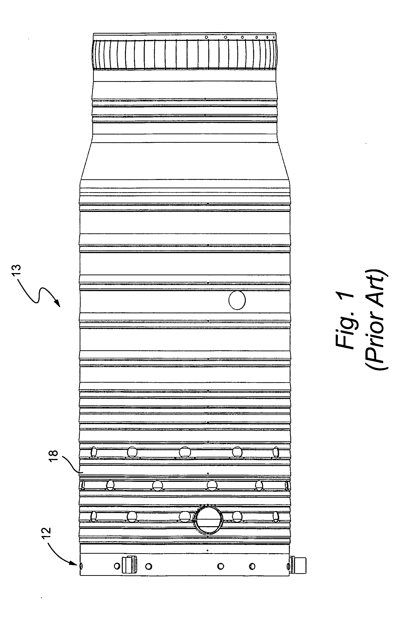
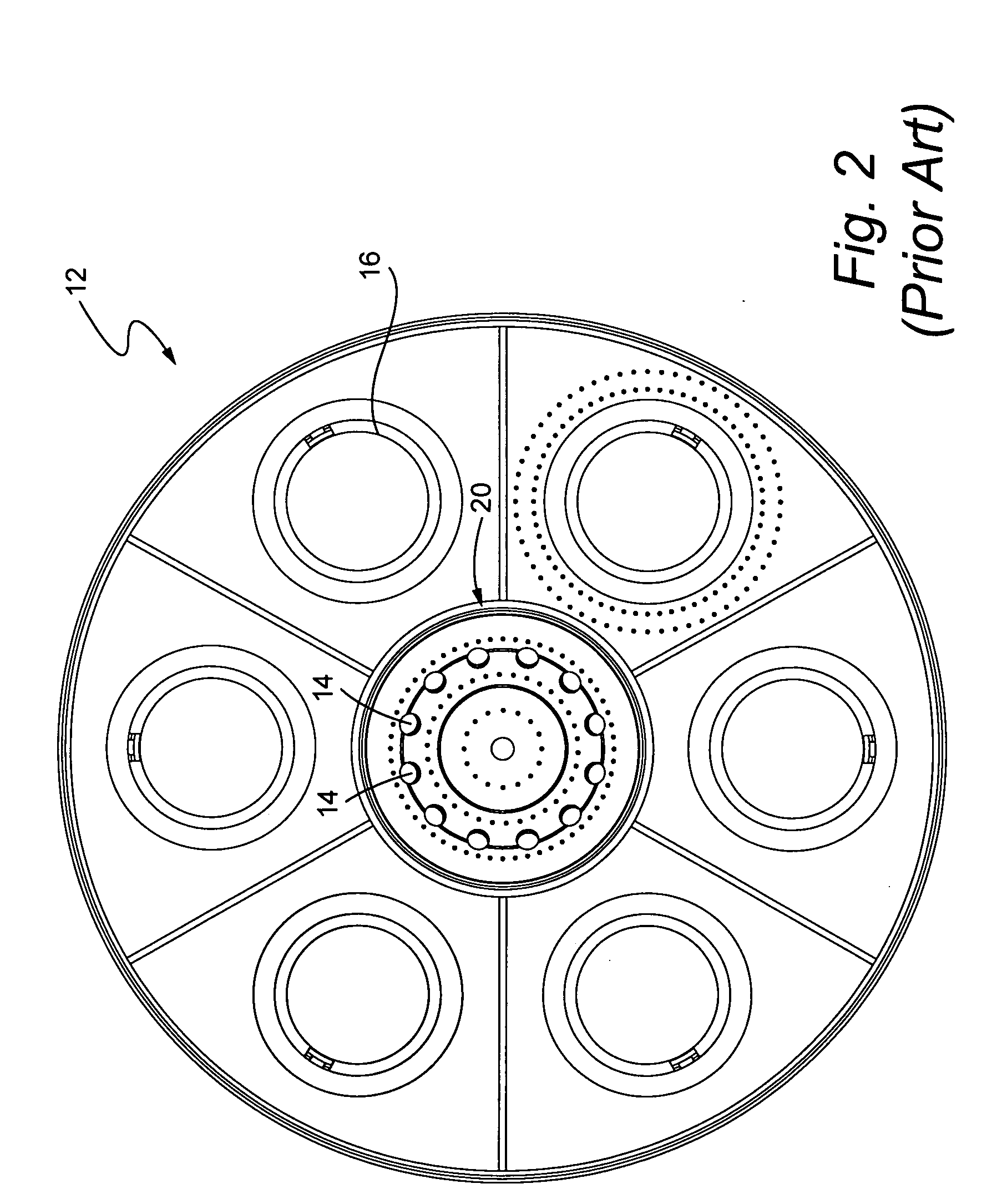
[0018]The conventional MNQC cap and liner assembly schematically illustrated in FIGS. 1-3, used for Syngas combustion was found to experience increased CO emissions as the oxygen concentration decreased in the core or center region of the combustor. In an example embodiment of the invention, the oxygen level in the core region is increased. More specifically, the oxygen level is increased in the core region by replacing the conventional small jets that straddled the fuel nozzles with large air mixing jets on the center body that are directed or aimed at each fuel jet. The resulting structure enables improved fuel air mixing in the core, shifted CO emissions turn-up point, increased diluent injection, wider range of operation, and lower NOx emissions.

[0019]NOx and CO reduction is limited by insufficient oxygen concentration in the combustor core region. Therefore, conventionally, the combustor was operated near unity in order to achieve stable operations while handling the high dilue...


PUM


Abstract

A combustor liner cap including a cap center body portion and a fuel nozzle portion defined peripherally of the cap center body portion. A plurality of fuel nozzle ports are defined through the fuel nozzle portion and a plurality of air jet holes are defined through the cap center body portion, and each air jet hole is aligned along a radius of the liner cap with a respective fuel nozzle port.

Description

BACKGROUND OF THE INVENTION[0001]This invention relates to gas and liquid fuel turbines and more specifically to combustors in industrial gas turbines used in power generation plants.[0002]Gas turbines generally include a compressor, one or more combustors, a fuel injection system and a turbine. Typically, the compressor pressurizes inlet air which is then turned in direction or reverse flowed to the combustors where it is used to cool the combustor and also to provide air to the combustion process. In a multi-combustor turbine, the combustors are located about the periphery of the gas turbine, and a transition duct connects the outlet end of each combustor with the inlet end of the turbine to deliver the hot products of the combustion process to the turbine.[0003]In an effort to reduce the amount of NOx in the exhaust gas of a gas turbine, inventors Wilkes and Hilt devised the dual stage, dual mode combustor which is shown in U.S. Pat. No. 4,292,801 issued Oct. 6, 1981 to the assig...

Claims


Application Information

Patent Timeline
Patent Type & Authority Applications(United States)
IPC IPC(8): F02C7/22
CPCF23C2900/06042F23R3/10F23R2900/00002F23R3/346F23R3/28
Inventor LIPINSKI, JOHNSIMONS, GIRARDBERRY, JONATHAN DWIGHTSOM, ABHIJIT
Owner GENERAL ELECTRIC CO
Why Eureka
Try Eureka