Limit lights

a technology of limit lights and switches, applied in the field of lift systems, can solve the problems of mechanical switches the click sound used to check the location of travel limit switches is soft in sound volume and difficult to hear, and the travel limit switches are subject to being broken and/or dislodged, etc., to facilitate faster and more reliable setting, facilitate assembly work, and facilitate the effect of quick and reliable setting

Inactive Publication Date: 2009-09-10
J R CLANCY
View PDF23 Cites 4 Cited by
  • Summary
  • Abstract
  • Description
  • Claims
  • Application Information

AI Technical Summary

Benefits of technology

[0022]Various embodiments of the present invention may be advantageous in that they may solve or reduce one or more of the potential problems and / or disadvantages discussed above in the previous two paragraphs. At least some embodiments of the present invention can make the assembler's job easier and can facilitate quicker and more reliable setting of the location of travel limit switches in the lift system, especially for noisy theatrical applications where it is difficult to hear the click of the travel limit switch being set into position. Also, miswiring problems can be more readily identified because the “wrong” light will light up if the travel limit switches have been mixed up. In some preferred embodiments of the present invention, different colored indicator lights are used for the different travel limit switches so that the color, as well as the position of the light, makes it clear to the installer which travel limit switch has been tripped at any given time during the installation process.
[0023]The present invention is directed to a lift system including a visual indicator device (for example, an LED indicator light) in data communication with the travel limit switches so that tripping of the travel limit switches (or at least the travel limit switches that are manually set by a human assembler) will cause the visual indictor device to make a visual indication that can be readily observed by the human assembler. The visual indication of the present indication can helpfully replace the conventional method of listening for the click. the present invention is further directed to a method of setting up a lift system including the use of a visual indication to help set the location of at least one of the travel limit switches.

Problems solved by technology

One potential problem is that the click sound used to check the location of the travel limit switch is soft in sound volume and difficult to hear, especially amidst the chaotic and high volume noise of the setup of a theatrical production or other construction site.
A related potential problem is that other ambient noises can be mistaken for a click, causing the operator to (temporarily until investigating) think that a travel limit switch undergoing set up has been tripped when it has, in fact, not been tripped.
Another problem is that some mechanical switches are subject to being broken and / or dislodged if the striker member pushes them too far.
What this means is that if an assembler misses the click sound and, as a result, continues to move the load and correlated striker in anticipation of the missed click sound, then the switch and / or switch mounting hardware may break.
Still another potential disadvantage is that listening for the click, in the din of a construction site, becomes something of a learned skill that requires experience and training.
Also, it means that people with less than perfect hearing cannot set travel limit switches during lift system set up.
This is a serious problem, especially when the corrective action taken by the lift controls upon striking the upper limit switch is different than the corrective action taken by the lift controls upon striking the lower limit switch.
Also, miswiring problems can be more readily identified because the “wrong” light will light up if the travel limit switches have been mixed up.

Method used


Image

  • Limit lights
  • Limit lights
  • Limit lights

Examples


Embodiment Construction

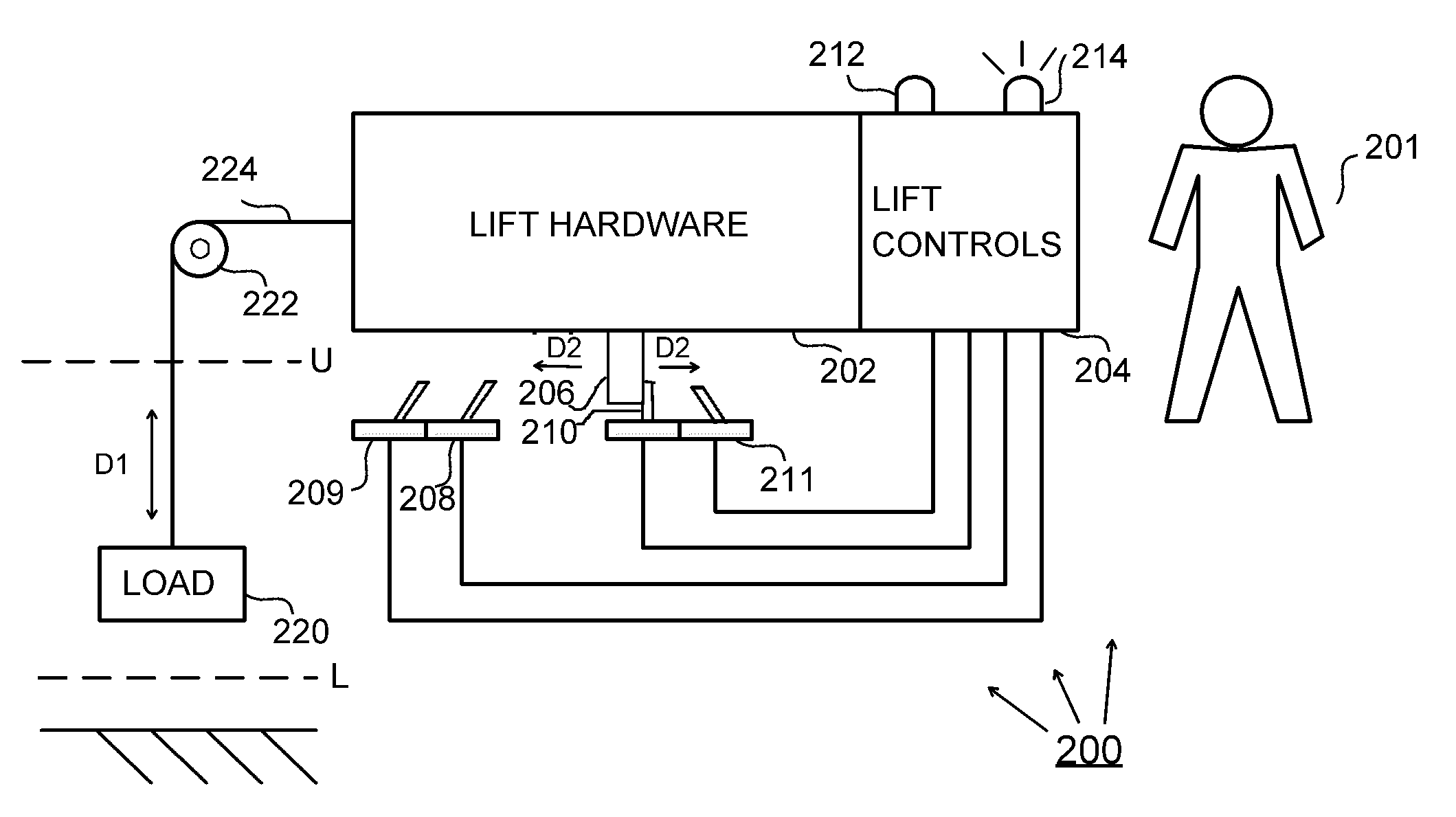
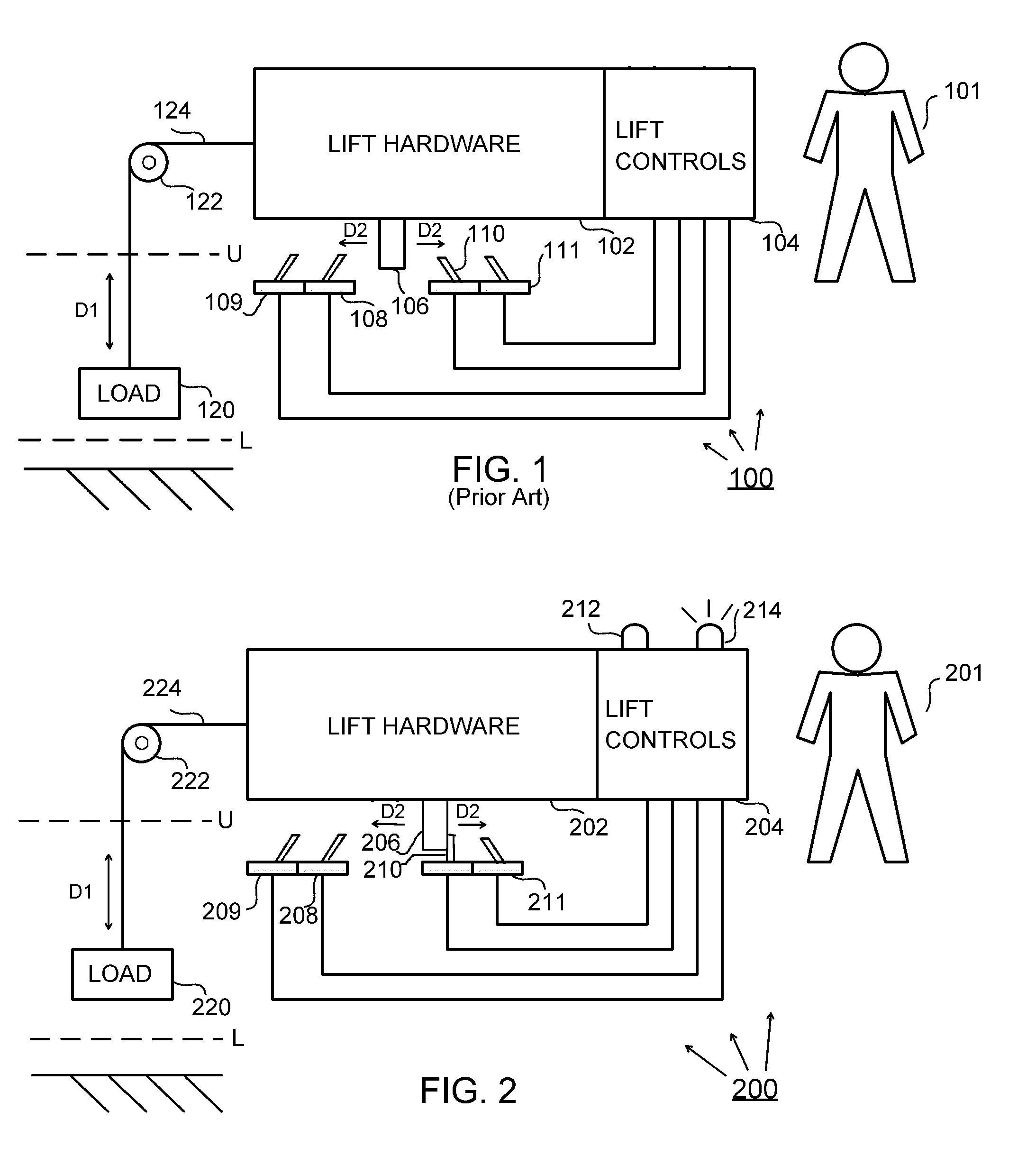
[0032]FIG. 2 shows lift system 200 according to the present invention including: lift hardware 202; lift controls 204; striker member 206; primary lower travel limit switch 208; primary lower travel limit switch 209; primary upper travel limit switch 210; secondary upper travel limit switch 211; lower limit indicator light 212; upper limit indicator light 214; load 220; loft blocking sub-system 222; and cable 224.

[0033]Primary lower travel limit switch 209 is in data communication with lower limit indicator light 212 through lift controls 204. Primary upper travel limit switch 210 is in data communication with lower limit indicator light 214 through lift controls 204. As shown in FIG. 2, when striker member 206 moves, in a manner correlated with the lifting of load 220 so that it comes into contact with a rotatable member built into switch 210, then the striker member forms a switch tripping connection with switch 210 and thereby trips switch 210. Indicator light 214 receives data e...


PUM


Abstract

A lift system including a visual indicator device (for example, an LED indicator light) in data communication with travel limit switches so that tripping of the travel limit switches (or at least the travel limit switches that are manually set by a human assembler) will cause the visual indictor device to make a visual indication that can be readily observed by the human assembler. The visual indication of the present indication can helpfully replace the conventional method of listening for a click during the step of setting the location of the travel limit switch when the lift system is initially set up by a human assembler. Instead of listening for a click, the assembler can watch for a visual indication by the visual indicator device, such as the lighting of an LED. this can make the assembler's job easier and can facilitate quicker and more reliable setting of the location of travel limit switches in the lift system. Also, the correspondence between travel limit switches and indicator lights makes it much less likely that the installer will miswire the indicator lights.

Description

RELATED APPLICATION[0001]The present application claims priority to U.S. provisional patent application No. 61 / 034,568, filed on Mar. 7, 2008; all of the foregoing patent-related document(s) are hereby incorporated by reference herein in their respective entirety(ies).BACKGROUND OF THE INVENTION[0002]1. Field of the Invention[0003]The present invention relates to lift systems (see DEFINITIONS section) and more particularly to lift systems for theatrical applications.[0004]2. Description of the Related Art[0005]Indicator lights are known. One example of this is U.S. Pat. No. 4,750,294 (“Lafontaine”) which discloses a power operated door that includes: (i) a limit switch that is tripped to enable field adjustment of a safety mechanism; and (ii) an indicator light indicating when the limit switch is activated. Lafontaine does not disclose or otherwise contemplate any sort of lift system.[0006]Lift systems having indicator light(s) to indicate certain conditions are known. One example o...

Claims


Application Information

Patent Timeline
Patent Type & Authority Applications(United States)
IPC IPC(8): B66B3/02
CPCB66B3/026
Inventor ZORN, THOMAS ALAN
Owner J R CLANCY
Why Eureka
Try Eureka