Coiled tubing well intervention system and method

Active Publication Date: 2009-09-10
DEVIN INT
View PDF3 Cites 6 Cited by
  • Summary
  • Abstract
  • Description
  • Claims
  • Application Information

AI Technical Summary

Benefits of technology

[0011]An advantage of the present invention is that the system disclosed allows an operator to utilize coiled tubing and jointed pipe together in an operational environment. Yet another advantage is that the apparatus can be used on offshore platforms. Yet another advantage is that the well intervention work utilizing the apparatus and method do not require a drilling rig. Still yet another advantage is that rigging up and rigging down of a coiled tubing unit is facilitated.
[0012]A feature of the present invention is the tower used for making-up and breaking-down the jointed tubulars. The tower can also be used for supporting the coiled tubing injector head. In the most pref

Problems solved by technology

As well understood by those of ordinary skill in the art, drilling rigs and snubbing units produce a large foot print and the cost can be quite significant.
Put another way, well intervention work with a drilling rig and/or snubbing units can be very expensive.
In the case where jointed pipe is used, an operat

Method used


Image

  • Coiled tubing well intervention system and method
  • Coiled tubing well intervention system and method
  • Coiled tubing well intervention system and method

Examples


Embodiment Construction

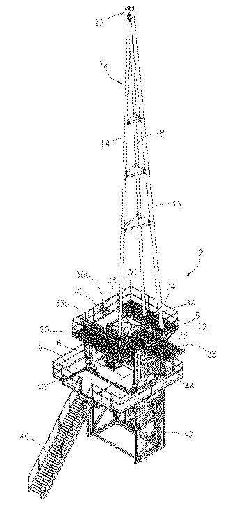
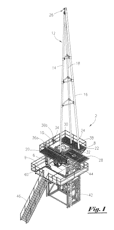
[0018]Referring now to FIG. 1, a schematic illustration of the most preferred embodiment of the present disclosure will now be disclosed. In FIG. 1, the apparatus 2 is situated on a platform (not shown in this view), and wherein the apparatus 2 is capable of performing well intervention operations with a coiled tubing unit (the coiled tubing unit not seen in this view). The apparatus 2 includes a modular support frame 6 with a top deck 8 and bottom deck 9, and wherein the top deck has a passage 10 therein. The apparatus 2 further includes a tower 12 mounted on the top deck 8.

[0019]As seen in FIG. 1, in the most preferred embodiment, the tower 12 is a three legged member (sometimes referred to as a tripod 12). The tower 12 includes leg 14, leg 16, and leg 18. Leg 14 is attached to the top deck 8 at 20; leg 16 is attached to the top deck at 22; leg 18 is attached to the top deck 8 at 24. A pulley means 26 is located at the apex of the tower 12, and wherein the pulley means 26 can be u...


PUM


Abstract

An apparatus and method for performing well intervention work with coiled tubing and jointed tubulars from a platform. The apparatus includes a modular support frame with a top deck, wherein the deck has a passage therein, and a tower mounted on the top deck. The apparatus further comprises a movable plate positioned within the passage, with the movable plate having a first aperture and a second aperture therein, and a track formed within the passage, and wherein the movable plate is slidingly attached to the track. The apparatus may further comprise a support rotary table disposed within the modular support frame, wherein the support rotary table suspends the jointed tubulars. The apparatus may further comprise a coiled tubing injector head interface plate operatively attached to the movable plate, and wherein the coiled tubing injector head plate is positioned over the first aperture of the movable plate. The first aperture is positioned over the well in a first position. A rotary table is positioned over the well in a second position.

Description

BACKGROUND OF THE INVENTION[0001]This invention relates to an apparatus and method for performing well intervention work. More particularly, but not by way of limitation, this invention relates to an apparatus and method for performing coiled tubing well intervention operations with jointed tubulars from a platform.[0002]In the drilling, completion and production of hydrocarbons, an operator may find it necessary to perform various well intervention work. Prior art techniques of performing well intervention work include utilizing traditional drilling rigs and snubbing units. As well understood by those of ordinary skill in the art, drilling rigs and snubbing units produce a large foot print and the cost can be quite significant. Put another way, well intervention work with a drilling rig and / or snubbing units can be very expensive.[0003]One alternative to the large and expensive rigs is for an operator to utilize coiled tubing. As appreciated by those of ordinary skill in the art, c...

Claims


Application Information

Patent Timeline
IPC IPC(8): E21B19/22
CPCE21B19/22
Inventor MONCUS, JAMES DEVINMILLER, JR., JOSEPH HAYDEN
Owner DEVIN INT
Why Eureka
Try Eureka