Speed based fluid control for dust reduction in the mining industry having gui user-interface

Inactive Publication Date: 2009-09-10
HOISINGTON CHARLES +2
View PDF12 Cites 37 Cited by
  • Summary
  • Abstract
  • Description
  • Claims
  • Application Information

AI Technical Summary

Benefits of technology

[0007]In another aspect, a system and apparatus is provided including a vehicle, multiple fluid applicators mounted thereto and a fluid conduit supplying fluid to said applicators from a reservoir, the system and apparatus for applying a fluid to road surfaces used in open pit mining sites, as required by the Environmental Protection Agency, the system and apparatus comprising a hydraulic pump driven by the engine of the vehicle, a hydraulic motor driven by the flow of hydraulic fluid provided thereto (wherein the speed of the motor is proportional to the flow of the applied hydraulic fluid), a hydraulic value coupled between the hydraulic pump and the hydraulic motor for controlling the flow of hydraulic fluid to the hydraulic motor, a fluid application pump driven by the hydraulic motor and for providing the fluid to be applied to the road surface to the fluid applicators, wherein an amount of application fluid pumped by the fluid application pump is proportional to the speed of the hydraulic motor, a speed sensor for detecting the speed of the vehicle and for generating a signal indicative of the detected speed, and a control apparatus having a control coupling to the hydraulic value and the multiple fluid applicators for controlling the application of the fluid to the road surface. The control apparatus comprising a programmable logic controller having an input for receiving the detected speed signal, and responsive thereto controlling the speed of the hydraulic motor via the flow from the hydraulic valve for enabling a controlled amount of application fluid to be provided to the multiple fluid applicators in relation to the detected vehicle speed, and a touch screen graphical user interface in communication with the logic controller for enabling a user to select from a plurality of programmed responses provided by the logic controller, wherein each one of the selections enables a different controlled amount of application fluid to be applied to the road surface.
[0008]In another aspect, a system and apparatus is provided for applying a sprayed fluid from a delivery vehicle to a surface, comprising a fluid pump for providing the fluid to a plurality of spray heads (where the fluid is stored in a reservoir and provides

Problems solved by technology

Problems involved in maintaining a consistent density of sprayed liquid from a vehicle have long been recog

Method used


Image

  • Speed based fluid control for dust reduction in the mining industry having gui user-interface
  • Speed based fluid control for dust reduction in the mining industry having gui user-interface
  • Speed based fluid control for dust reduction in the mining industry having gui user-interface

Examples


Embodiment Construction

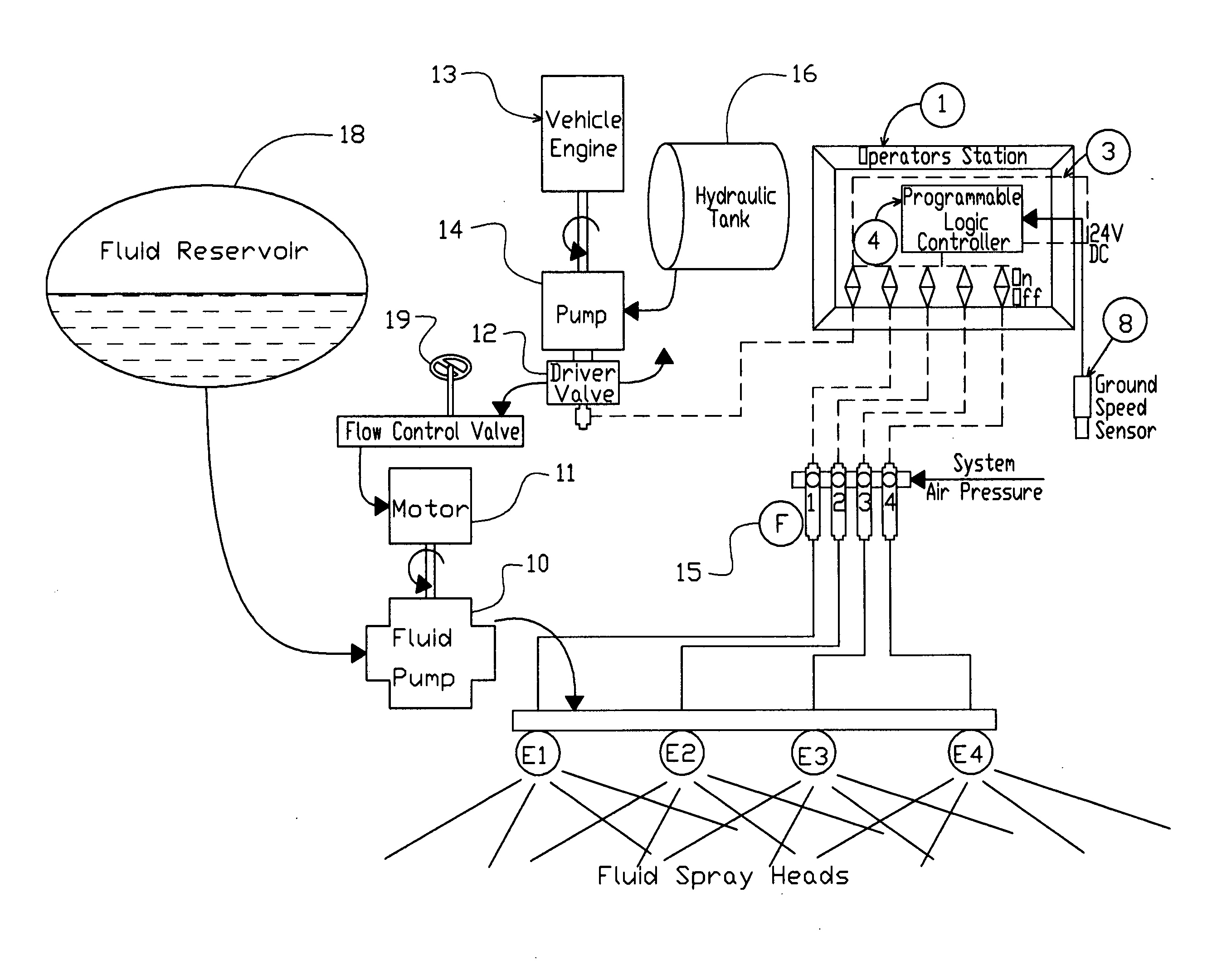
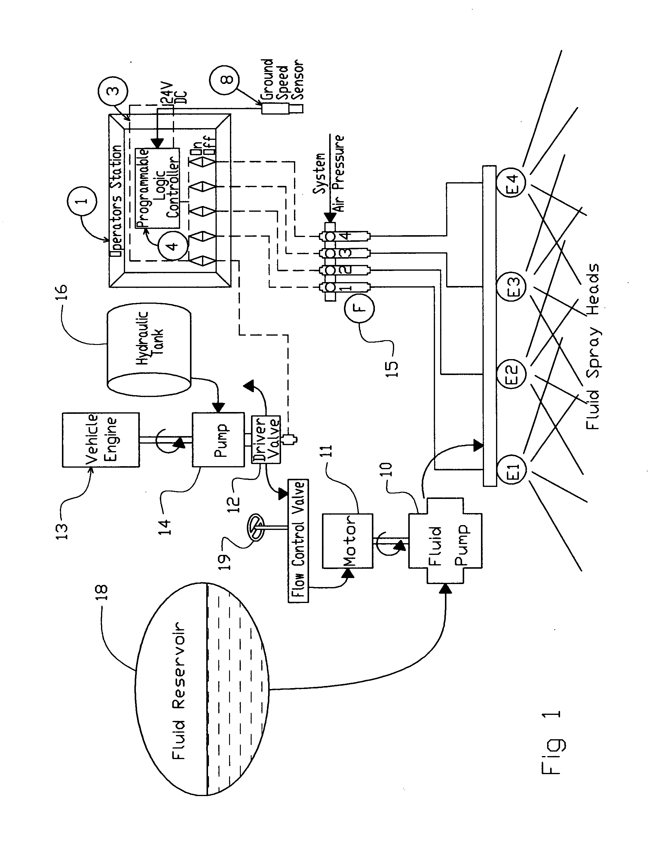
[0016]Referring to FIG. 1, there is shown a schematic of a system in accordance with an embodiment of the present invention. The FIG. 1 is a schematic of a system utilizing a PLC 4 to control application of a fluid and which can be integrated with a vehicle. A PLC as an advantage over other computing devices because PLCs are better armored for severe conditions (dust, moisture, heat, cold, etc., as is the type of conditions seen in the open pit mining industry) and have the facility for extensive input / output (I / O) arrangements. These are used to connect the PLC 4 to sensors and actuators to perform the functions presently described. On the actuator side, the PLC 4 can operate electric motors, pneumatic or hydraulic cylinders, magnetic relays or solenoids, or analog outputs. The PLC 4 contains input and output devices compatible with industrial pilot devices and controls; little electrical design is required, and the design problem centers on expressing the desired sequence of opera...


PUM


Abstract

A system and apparatus for controlling the delivery of fluid from a reservoir, in relation to the ground speed of the vehicle delivering the fluid. Including a system where a hydraulic pump and motor are the components to drive the delivery of the fluid from the reservoir. The hydraulic motor is controlled to vary the output of the fluid pump based on a programmable logic controller (PLC) program. Where an operator selects the desired density of fluid to be pumped, the PLC controls fluid pump flow by controlling the hydraulic motor speed based on the vehicle ground speed

Description

TECHNICAL FIELD[0001]The present invention relates to fluid control and, more specifically, a system and apparatus for controlling the delivery of a fluid to a surface.BACKGROUND OF THE INVENTION[0002]Problems involved in maintaining a consistent density of sprayed liquid from a vehicle have long been recognized. For example, in a vehicular sprayer of the type having a number of spray heads and a pump for pumping liquid to the spray heads, it has been the practice to manually preset either the pump speed or the spray head pressure for a particular vehicle speed for operation only at that particular speed. However, it is not convenient or even possible to maintain a precise vehicular speed during spraying.[0003]There are numerous applications in which it is necessary to continuously control the dissemination of a fluid from a reservoir, through control of the fluid pump motor speed. There are, for example, numerous agricultural and contracting operations in which tank trucks are used...

Claims


Application Information

Patent Timeline
IPC IPC(8): B05B3/18
CPCA01B79/005A01C23/007B05B9/0409B05B9/0423E01H3/02B05B12/126B05B13/005E01C19/176B05B9/06
Inventor HOISINGTON, CHARLESHOESINGTON, GARRETT C.ROLFE, CHAD
Owner HOISINGTON CHARLES
Why Eureka
Try Eureka