Hammer

a technology of hammer and hammer blade, which is applied in the field of hammers, can solve the problems of requiring immediate maintenance and repair, severe damage to the hammermill, and wear of the hammer blade over a relatively short period of operation, and achieves the effect of improving the hardness of the hammer blade or the tip, and improving the rotational securement of the hammer

Active Publication Date: 2009-09-10
GENESIS III
View PDF9 Cites 8 Cited by
  • Summary
  • Abstract
  • Description
  • Claims
  • Application Information

AI Technical Summary

Benefits of technology

[0012]The improvement disclosed and described herein centers on an improved hammer to be used in a hammermill. This hammer, although not limited to grains, has been specifically developed for use in the grain industry. The various embodiments disclosed herein for the hammer are for use in rotatable hammer mill assemblies for comminution. The hammer is compromised of a first end for securement of the hammer within the hammer mill. The second end of the hammer is opposite the first end and is configured for contacting material for comminution, and a hammer neck connects the first and second ends. The hammer typically requires treatment to improve the hardness of the hammer blade or tip. The hammer of the present art improves securement the hammer rotated, as well as the wear of the second end of the hammer.

Problems solved by technology

One significant problem with hammermills is the wear of the hammers over a relatively short period of operation in reducing “dirty” products, which include materials such as nails, dirt, sand, metal, and the like.
As found in the prior art, even though a hammermill is designed to better handle the entry of a “dirty” object, the possibility exists for catastrophic failure of a hammer causing severe damage to the hammermill and requiring immediate maintenance and repairs.
If rigidly attached hammers contact such a non-crushable foreign object within the hammermill assembly housing the consequences of the resulting contact can be severe.
However, because the weight of the hammer increased, the capacity of the unit typically will be decreased because of horsepower limitations.

Method used


Image

  • Hammer
  • Hammer
  • Hammer

Examples


first embodiment

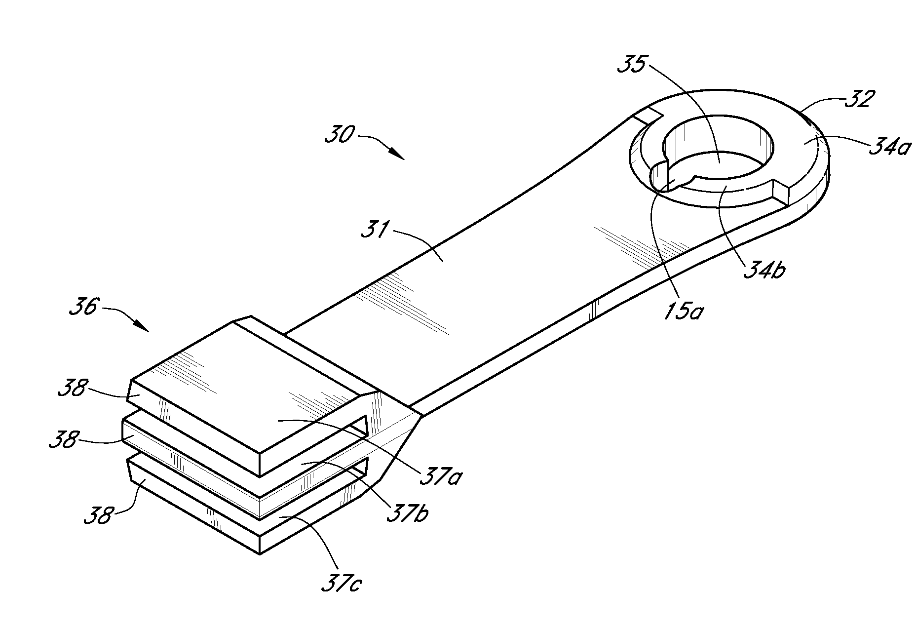
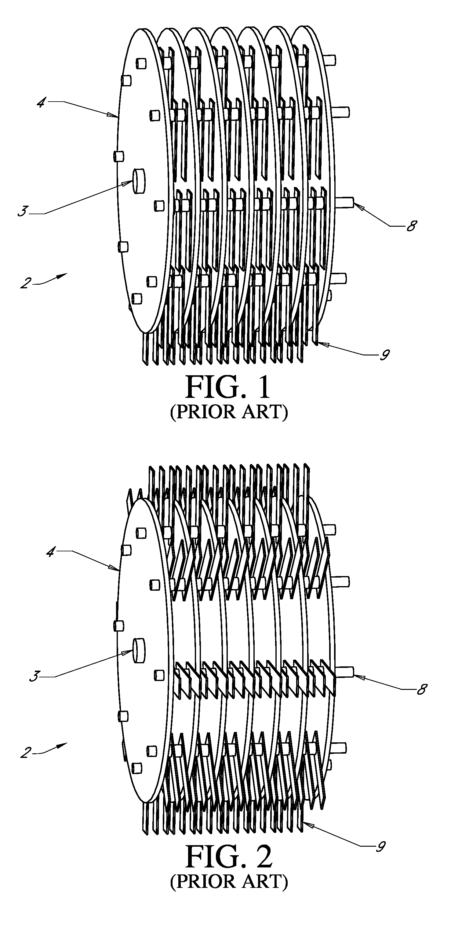
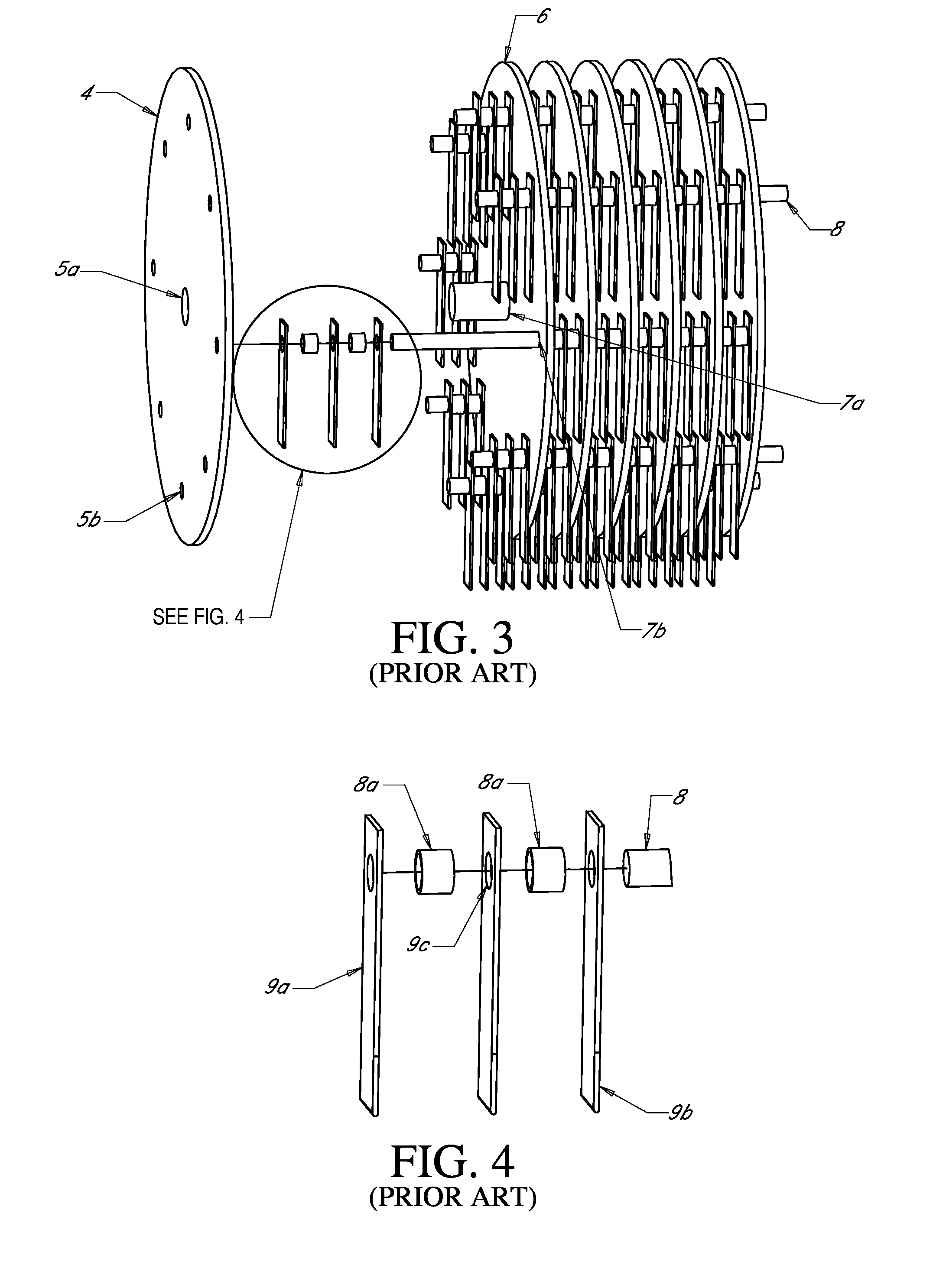
[0054]FIGS. 5-6 show the notched hammer 10 for use in a rotatable hammermill assembly 2, which type of hammermill assembly 2 was previously described herein. The notched hammer 10 is comprised of a notched hammer first end 12 (also referred to herein occasionally as the securement end) for securement within the hammermill assembly 2 and a notched hammer second end 16 (also referred to herein occasionally as the contact end) for delivery of mechanical energy to and contact with the material to be comminuted. The notched hammer first end 12 is connected to the notched hammer second end 16 by a notched hammer neck 11. A notched hammer rod hole 15 is centered in the notched hammer first end 12 for engagement with and attachment of the notched hammer 10 to the hammer rod 8 of a hammermill assembly 2. Typically, the distance from the center of the notched hammer rod hole 15 to the most distal edge of the notched hammer second end 16 is referred to as the “hammer swing length.”

[0055]As sho...

second embodiment

[0059]The notched hammer neck 11 in the second embodiment is not as thick as the notched hammer first end 12 or the notched hammer second end 16. This configuration of the notched hammer neck 11 allows for reduction in the overall weight of the notched hammer 10, to which attribute the neck voids 11a also contribute. The mechanical energy imparted to the notched hammer second end 16 with respect to the mechanical energy imparted to the notched hammer neck 11 is also increased with this configuration. The neck voids 11a also allow for greater agitation of the material to be comminuted during operation of the hammermill assembly 2.

[0060]A third embodiment of the notched hammer 10 is shown in FIG. 9. The notched hammer rod hole 15 in the third embodiment includes a notched hammer first shoulder 14a and a notched hammer second shoulder 14b oriented symmetrically around the notched hammer rod hole 15. As explained in detail above for the first embodiment of the notched hammer 10, the fir...

third embodiment

[0061]The edges of the notched hammer neck 11 in the third embodiment are non-parallel with respect to one another, and instead form an hourglass shape. This shape starts just below the notched hammer rod hole 15 and continues through the notched hammer neck 11 to the notched hammer second end 16. This hourglass shape yields a reduction in weight of the notched hammer 10 and also reduces the vibration of the notched hammer 10 during operation.

[0062]A forth embodiment of the notched hammer 10 is shown in FIG. 10, which most related to the second embodiment of the notched hammer 10 shown in FIG. 8. The fourth embodiment does not include neck voids 11a. As shown, the fourth embodiment provides the benefits of increasing the surface area available for distribution of the opposing forces placed on the notched hammer rod hole 15 in proportion to the thickness of the notched hammer neck 11 without using a notched hammer first or second shoulder 14a, 14b. As with some other embodiments disc...


PUM


Abstract

A hammer for use in a rotatable hammermill assembly comprising a first end for securement within a hammermill assembly, wherein a rod hole is formed in the second end, wherein the rod hole is centered in the first end for engagement with and attachment to the hammermill assembly is disclosed. The hammer also has a second end for contact and delivery of momentum to material to be comminuted, wherein the second end includes at least two blades. A neck connects the first end to the second end. In some embodiments the thickness of the neck may be less than the thickness of the first end or of any of the blades. In some embodiments the rod hole is surrounded by one or more rod hole shoulders. In other embodiments a notch is positioned in the rod hole along the longitudinal axis thereof.

Description

CROSS REFERENCE TO RELATED APPLICATIONS[0001]Applicant states that this utility patent application claims priority from U.S. patent application Ser. No. 11 / 897,586 filed on Aug. 31, 2007 and is a continuation-in-part of said utility patent application, which claimed priority from and is a continuation-in-part of U.S. patent application Ser. No.11 / 544,526 filed on Oct. 6, 2006, which claimed priority from and is a continuation-in-part of U.S. patent application Ser. No. 11 / 150,430 filed on Jun. 11, 2005 now U.S. Pat. No. 7,140,569, which was a continuation-in-part of U.S. patent application Ser. No. 10 / 915,750 filed on Aug. 11, 2004, now abandoned, all of which are incorporated by reference herein in their entirety. Applicant also claims priority from provisional U.S. Pat. App. No. 61 / 068,214 filed on Mar. 5, 2008 and provisional U.S. Pat. App. No. 61 / 068,054 filed on Mar. 4, 2008, both of which are incorporated herein in their entirety.FIELD OF INVENTION[0002]The present invention r...

Claims


Application Information

Patent Timeline
Patent Type & Authority Applications(United States)
IPC IPC(8): B02C13/28
CPCB02C13/28B02C13/04
Inventor YOUNG, ROGER T.
Owner GENESIS III
Why Eureka
Try Eureka