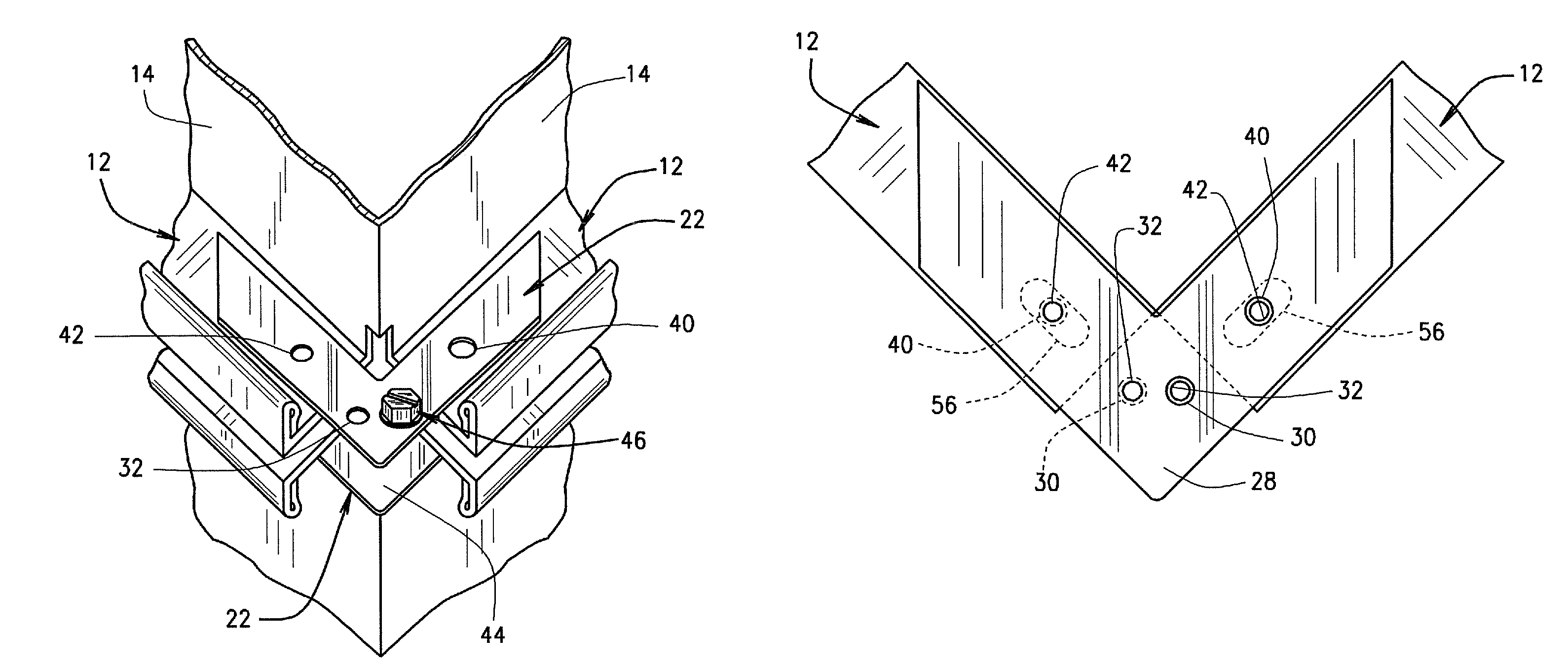
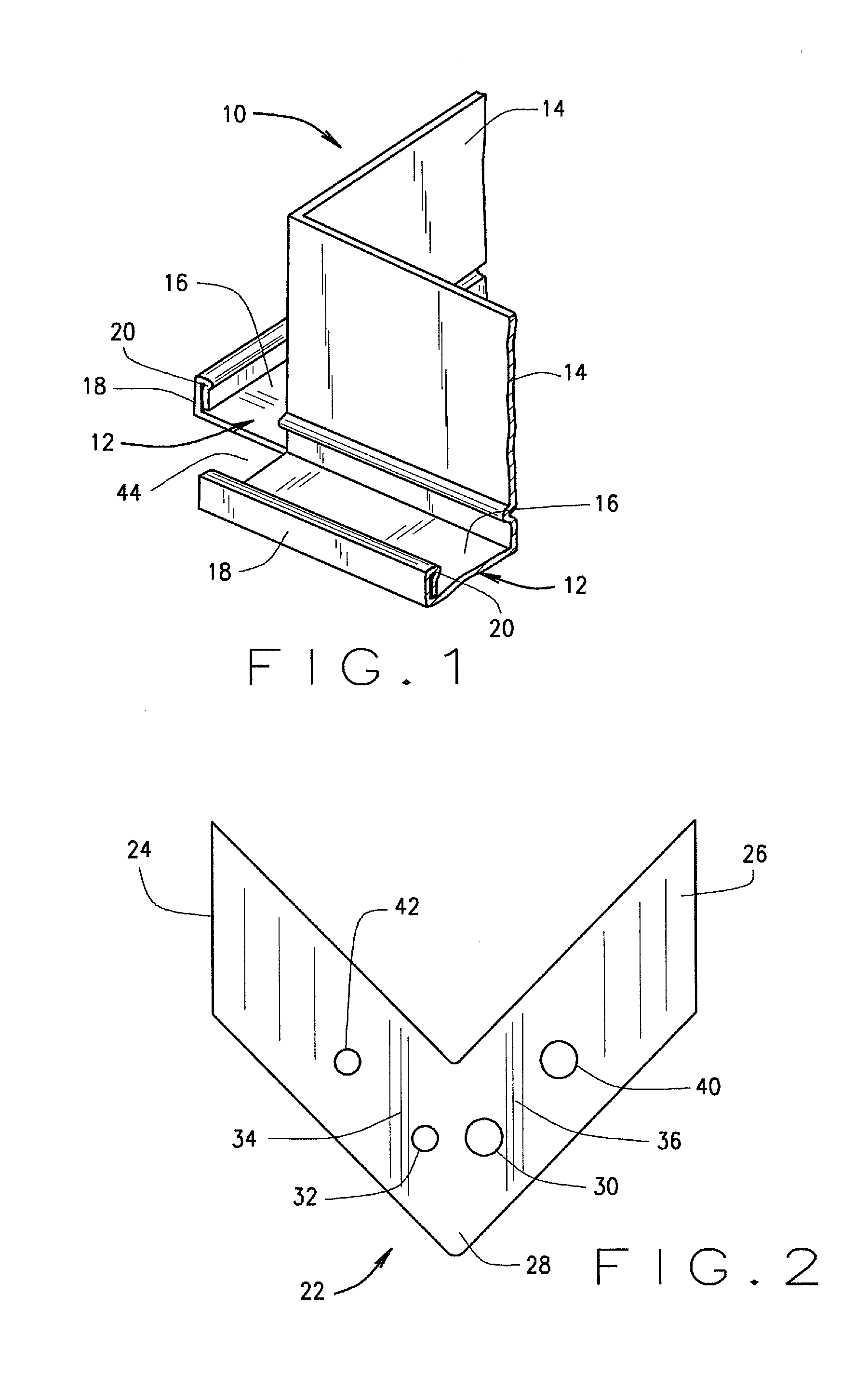
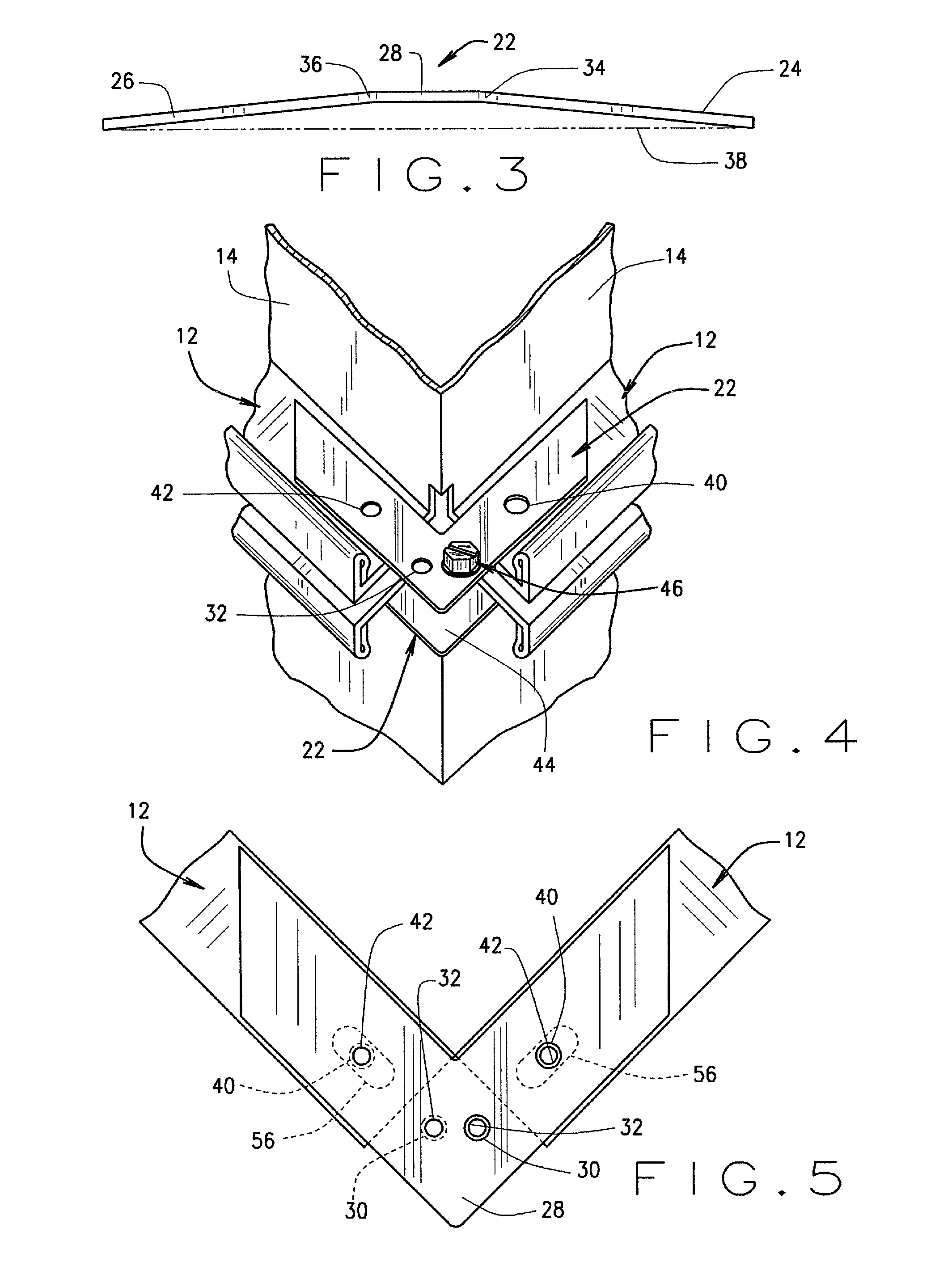
Sheet metal corner for duct flanges

a technology of corner flanges and duct flanges, which is applied in the direction of hose connections, lighting and heating apparatus, heating types, etc., can solve the problems that the channel flange does not always produce a completely secure connection, and achieves the effect of reducing the number of crimping

Active Publication Date: 2009-09-10
H J FISCHER
View PDF18 Cites 28 Cited by
  • Summary
  • Abstract
  • Description
  • Claims
  • Application Information

AI Technical Summary

Benefits of technology

[0011]In still other embodiments of the present corner flange connection member, the bowed configuration of such corner members can be eliminated and such corner flange connection members can be made so as to be substantially flat or planar. In this particular configuration, in one embodiment, the corner portion of such connector members may include a clearance hole and a tap hole as previously explained, and one leg portion may include a clearance hole while the other leg portion includes a tap hole.
[0013]Still further, although no pressing is required for initially inserting any of the present corner flange connection members within the respective duct channel flanges, the present connection members are sized and shaped so that crimping of the adjacent duct channel flanges onto the present corner flange connection members is likewise possible to further strengthen the joinder therebetween. Since the present corner flange connection members are substantially smooth and do not include upstanding side walls or any projections or protrusions similar to the projections associated with the angle plate disclosed in U.S. Pat. No. 5,342,100, the present corner flange connection members are both stackable and nestable within an automated corner plate installing machine and such corner flange connection members are likewise easily slidable from the bottom of a stack for use with such automated corner machines. In addition, since the present corner members include no upstanding side walls or side flanges, crimping is substantially easier since only the side wall of the duct channel flange need be crimped.
[0014]Still further, although traditional sheet metal screws or standard nuts and bolts can be used in clamping together adjacent duct sections, the present invention also includes the use of high-speed connector members in the form of a piloted self-tapping bolt, a piloted bolt in combination with a standard nut, a standard bolt or carriage bolt in combination with a piloted nut or piloted washered nut, a piloted self-tapping bolt with a relief portion between the head and threaded portion, a piloted carriage bolt in combination with a piloted nut, and a special sheet metal fastener, all of which provide improved drawing action. Each of these high-speed fastening connectors greatly improves the time required to accomplish the joinder and eliminates the use of clumsy hex nuts and washers. These improved fastening members likewise substantially eliminate cross-threading and misalignment of the nut and bolt combination and, importantly, all of these fastening members can be quickly inserted through the use of a battery powered drill or other power tool.

Problems solved by technology

This snap or pressing connection of the corner plate into the duct channel flange does not always produce a completely secure connection, even when crimping is used.

Method used


Image

  • Sheet metal corner for duct flanges
  • Sheet metal corner for duct flanges
  • Sheet metal corner for duct flanges

Examples


embodiment 70

[0052]FIG. 11 illustrates still another embodiment 70 of a high-speed fastener member for use with the present corner elements 22, the embodiment 70 including a standard bolt 72 and a piloted nut 74. The standard bolt 72 includes a head portion 76 and a threaded portion 78 and the piloted nut 74 includes a non-threaded cavity 80 and a threaded cavity 82. The non-threaded cavity 80 is of a diameter larger than the threaded portion 78 of bolt 72 and larger than the threaded cavity 82 and extends along a portion of the overall length of the piloted nut 74 as illustrated in FIG. 11. The piloted nut 74 could also be a piloted washered nut. The slightly oversized non-threaded cavity 80 serves as a guide mechanism for properly orienting the threaded portion 78 of the standard bolt 72 into the nut 80 before engaging the threaded cavity 82. Like the piloted portions 52 and 68 associated with fasteners 46 and 58, the non-threaded cavity 82 allows the nut 76 to be properly positioned relative ...

embodiment 160

[0068]Joinder of adjacent duct sections utilizing adjacent opposed corner elements 142 can be accomplished through the use a conventional carriage type bolt. In this regard, FIG. 19 illustrates still another embodiment 160 of a high-speed fastener member for use with the present corner elements 142, the embodiment 160 including a standard carriage bolt 162 and a piloted nut 164. The standard carriage bolt 162 includes a head portion 166, a rectangularly shaped relief portion 168, and a threaded portion 170. The piloted nut 164 includes a non-threaded cavity 172 and a threaded cavity 174. The non-threaded cavity 172 is of a diameter larger than the threaded portion 170 of carriage bolt 162 and larger than threaded cavity 174 and extends along a portion of the overall length of the piloted nut 164 as illustrated in FIG. 19. Similar to fastener member 70 illustrated in FIG. 11, the slightly oversized non-threaded cavity 172 serves as a guide mechanism for properly orienting the threade...


PUM

PropertyMeasurementUnit
diameteraaaaaaaaaa
heightaaaaaaaaaa
distanceaaaaaaaaaa

Abstract

The present invention relates to various embodiments of an improved high-speed corner flange connection member which is specifically shaped and designed to increase the clamping force applied to adjacent duct flanges when adjacent duct sections are connected together. In some embodiments, the corner connection members include creases or bends which allows the leg portions to be bent or angularly deflected away from such creases downwardly so as to form a bowed configuration; some embodiments include clearance holes and tap holes which are strategically positioned on the corner element such that when a pair of duct sections are positioned in end-to-end relationship for joinder, the opposed corner elements are arranged such that a clearance hole is positioned in registration with a tap hole; other embodiments include similarly shaped openings which are associated with the respective opposed corner elements; and in still other embodiments a substantially flat corner element is constructed utilizing the strategically placed clearance and tap holes so as to achieve a faster and stronger connection including the use of standard carriage type bolts. Still further, the present invention includes the use of a plurality of differently configured high-speed fastener members which are specifically designed to substantially eliminate misalignment and cross-threading issues commonly associated when using the conventional bolt / washer / nut arrangement for fastening adjacent duct sections.

Description

CROSS REFERENCE TO RELATED APPLICATIONS[0001]This application is a non-provisional application claiming priority to provisional Patent Application Ser. No. 61 / 053,772 filed May 16, 2008, the entire disclosure of which is incorporated herein by reference.BACKGROUND OF INVENTION[0002]The present invention relates generally to duct assemblies for transporting pressurized fluid in buildings such as ductwork for HVAC systems and, more particularly, to various embodiments of a corner flange connection member for placement into corners defined by channel flanges associated with HVAC and other types of ductwork and the method for attaching such corner flange connection members to the ductwork channel flanges including certain improved high speed fastener connectors.[0003]Duct assemblies used to transport pressurized fluid in buildings such as forced air HVAC systems are conventionally formed in sections and secured together to form longer spans as needed. A duct section is typically formed ...

Claims


Application Information

Patent Timeline
Patent Type & Authority Applications(United States)
IPC IPC(8): F16L23/02F16L9/22
CPCF16L23/14Y10T29/49948F24F13/0209
Inventor FISCHER, HERBERT J.
Owner H J FISCHER
Why Eureka
Try Eureka