Filter circuit and method of controlling same

a filter circuit and filter technology, applied in the direction of process control, power conversion systems, instruments, etc., can solve the problems of decreasing the high-frequency impedance of the cmc, difficult to equalize the current that flows into the positive-side winding and the current that flows into the negative-side winding of each individual cmc used in the filter, and almost never achieved, so as to avoid the effect of reducing the impedan

Inactive Publication Date: 2009-09-10
NEC CORP
View PDF4 Cites 8 Cited by
  • Summary
  • Abstract
  • Description
  • Claims
  • Application Information

AI Technical Summary

Benefits of technology

[0015]Accordingly, an object of the present invention is to provide a filter circuit adapted so as to avoid a decline in impedance ascr

Problems solved by technology

In actuality, however, this state is almost never attained and it is difficult to equalize the current that flows into the positive-side winding and the current that flows into the negative-side winding of each individual CMC used in the filter.
More specifically, when a difference is produced between the positive and negative winding currents of the filter and an imbalance develops between the positive and negative winding currents of the CMC, a difference develops between a magnetic flux generated by the positive winding current and a magnetic flux negated by the negative winding cu

Method used


Image

  • Filter circuit and method of controlling same
  • Filter circuit and method of controlling same
  • Filter circuit and method of controlling same

Examples


Embodiment Construction

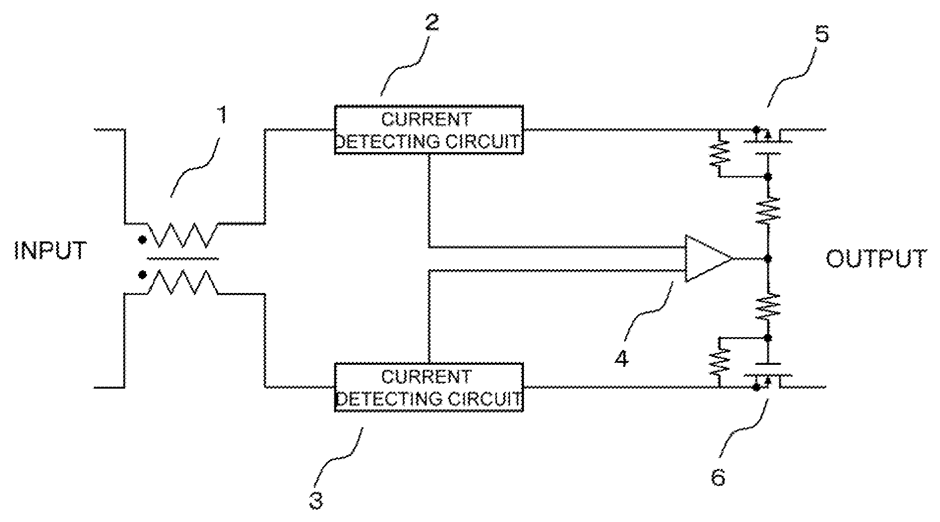
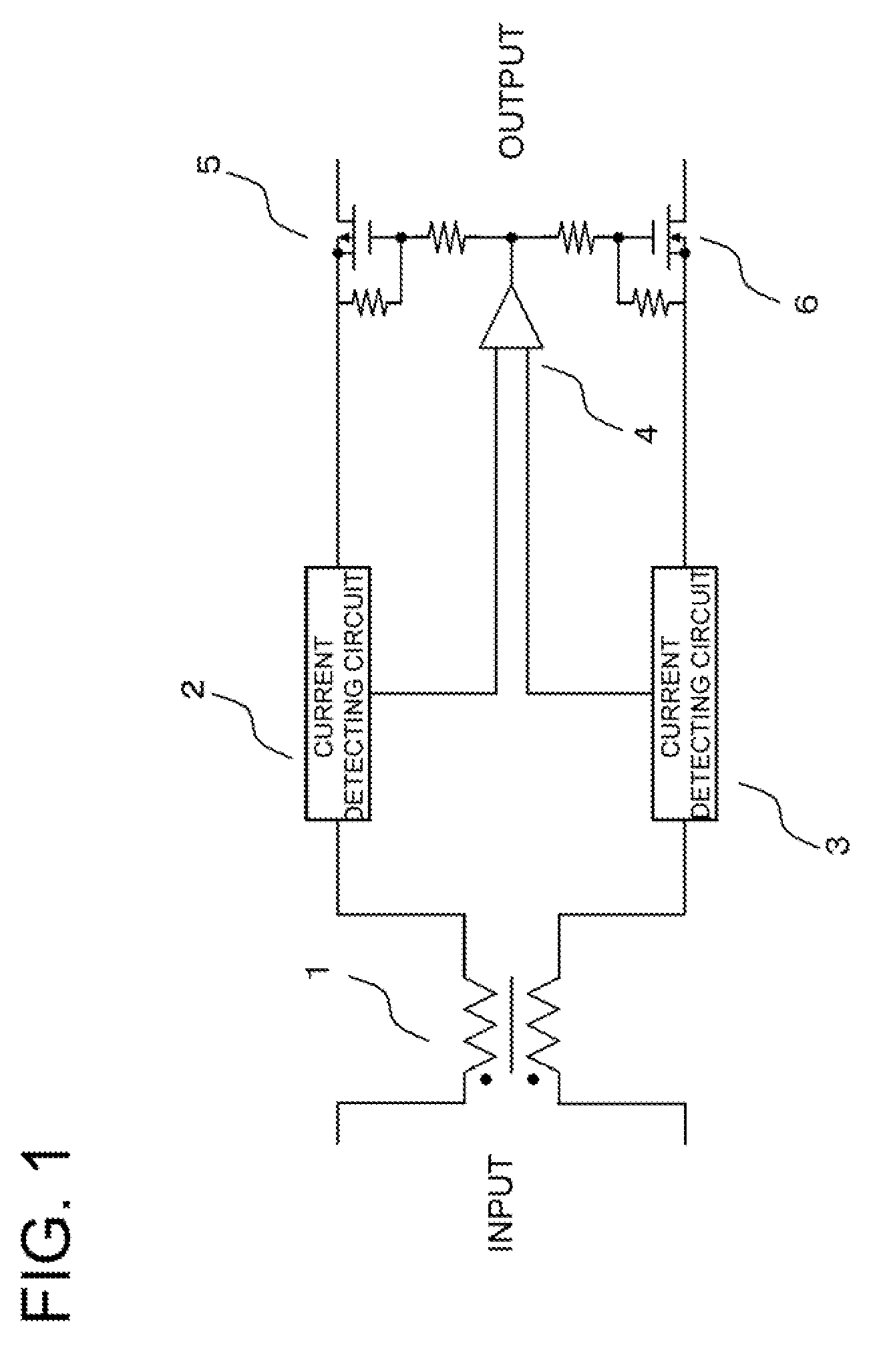
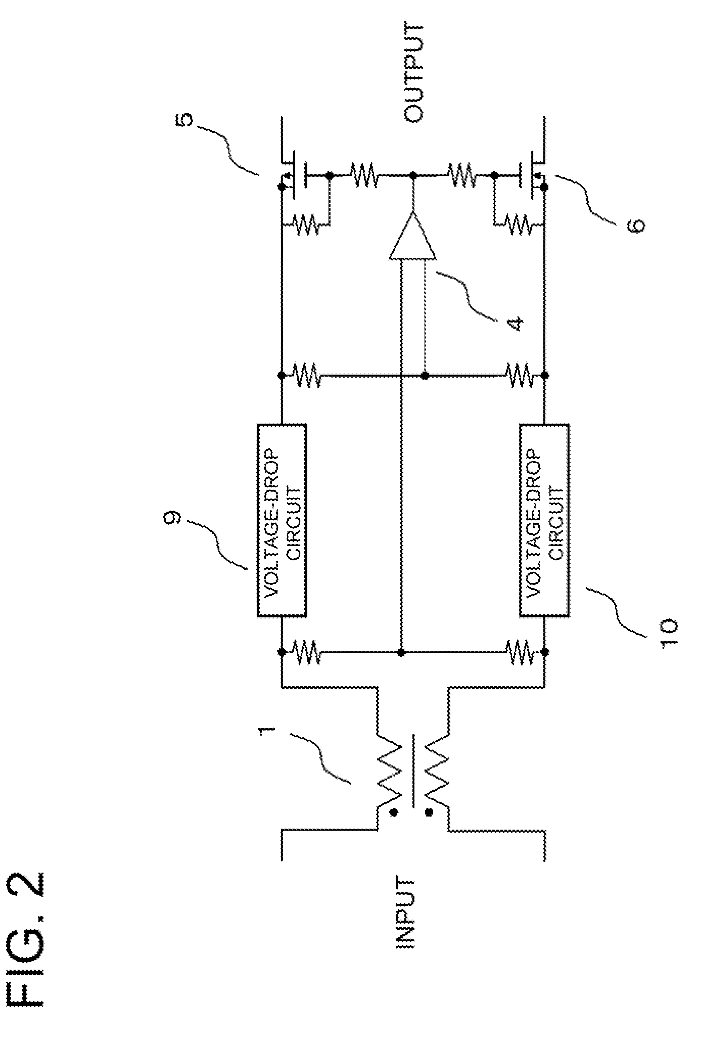
[0032]Exemplary embodiments of the present invention will be described below. In a case where a plurality of filter circuits are arranged in parallel, unless the currents that flow into the positive-side and negative-side windings of a common-mode choke coil (CMC) in each filter circuit are balanced, magnetic saturation occurs in the CMC, which uses a core material having a high magnetic permeability, and a normal filter characteristic can no longer be obtained, as described earlier.

[0033]Accordingly, in the present invention, it is so arranged that the currents that flow into the positive-side and negative-side windings are balanced so that a normal filter characteristic is obtained. More specifically, the currents that flow into the positive-side and negative-side windings of a CMC used in a filter circuit are monitored and automatically adjusted so as to become equal values. The desired filter characteristic is obtained even in a case where a plurality of filters are used.

[0034]F...


PUM


Abstract

Disclosed is a filter circuit that includes means for monitoring currents flowing through positive and negative windings of a common-mode noise filter, and means for performing an adjustment based on the result of monitoring so as to equalize the current flowing positive and negative windings.

Description

REFERENCE TO RELATED APPLICATION [0001]This application is based on and claims the benefit of the priority of Japanese patent application No. 2008-056538 filed on Mar. 6, 2008, the disclosure of which is incorporated herein in its entirety by reference thereto.FIELD OF THE INVENTION[0002]This invention relates to a filter circuit and, more particularly, to a filter circuit having a common-mode choke coil and a method of controlling this circuit.BACKGROUND ART[0003]In order to improve reliability and enhance the current supply capability in a filter having a common-mode choke coil, use is made of an arrangement (a redundant arrangement) in which a plurality of filter circuits alone or modules in which a filter circuit is additionally provided with a voltage monitoring function or over-current protection function (these are referred to as “filter modules”) are disposed in parallel.[0004]FIG. 4 is a diagram illustrating a typical example of an arrangement in which a plurality of filter...

Claims


Application Information

Patent Timeline
IPC IPC(8): G05F1/10
CPCH02M2001/123H02M1/12H02M1/123
Inventor TSUTSUMI, TSUYOSHIMATSUDA, EISHI
Owner NEC CORP
Why Eureka
Try Eureka