
Distributed jammer system

a jammer and distribution technology, applied in direction controllers, instruments, measurement devices, etc., can solve the problems of reducing the effectiveness of current expendable decoys, affecting the accuracy of jammer detection,

Inactive Publication Date: 2009-09-10
ELTA SYST LTD
View PDF6 Cites 47 Cited by
  • Summary
  • Abstract
  • Description
  • Claims
  • Application Information

AI Technical Summary

Benefits of technology

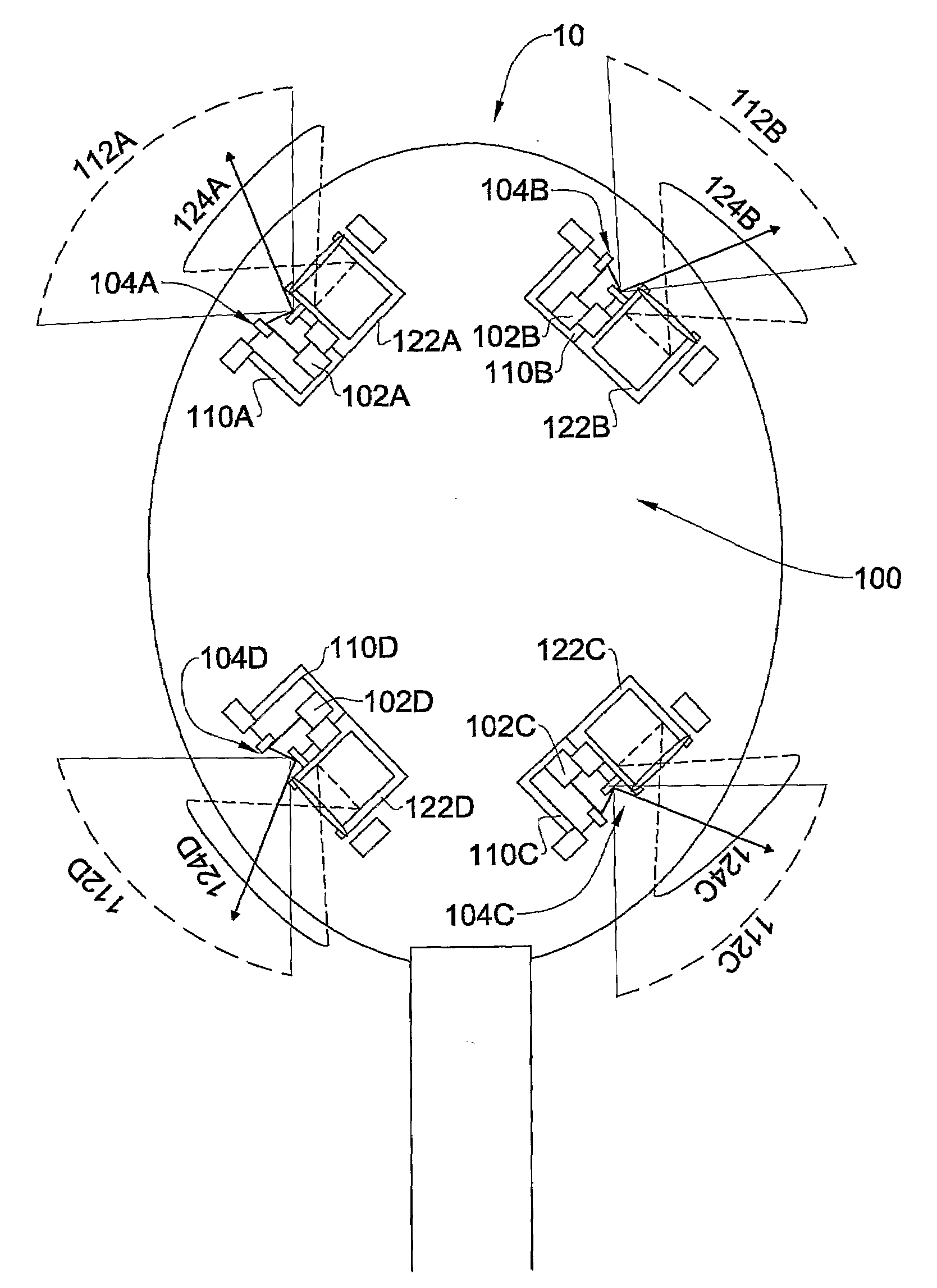
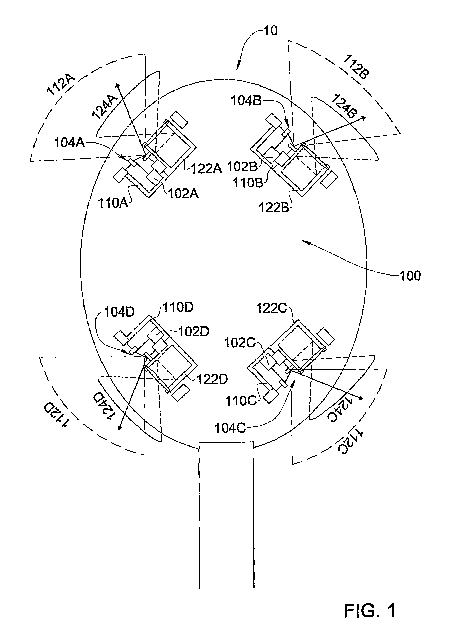
[0012]There is provided according to some embodiments of the invention a laser directed infrared countermeasures system (hereinafter: “LDIRCM system”) mountable on a platform. A LDIRCM system, and in particular the LDIRCM system of the present invention, is intended to provide protection against Infrared (IR) directed weapons. A LDIRCM system, and in particular the LDIRCM system of the present invention, may be part of a protection suite that is intended to provide protection against a variety of threats including IR directed weapons. However, a LDIRCM system according to the present invention may operate as a standalone system which is capable of providing various degrees of protection against a threat directed towards a platform on which the LDIRCM system is mounted, and in particular protection against a threat which uses an IR guidance system to target the protected platform.
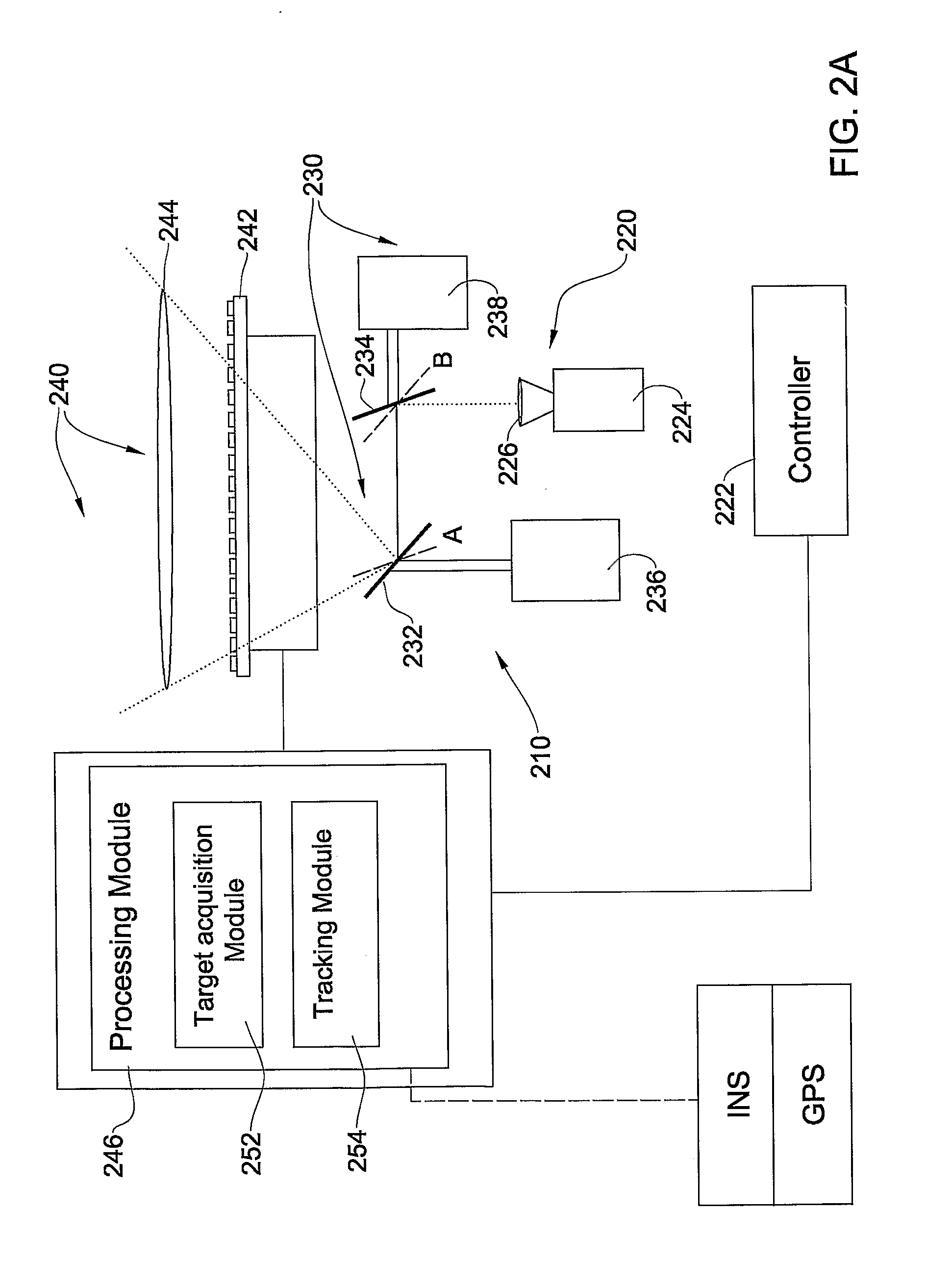
[0016]According to another aspect of the invention, the guidance module of a sector unit may include one or more beam steering elements rotatable about a first and a second axes. The rotation of the beam steering element(s) around the first and the second axis may enable the steering of at least a laser beam generated by the laser unit that is also part of the sector unit towards a threat. The beam steering element(s) may be configured so that a rotation of the beam steering element(s) about a first axis does not cause the orientation of the second axis to change.
[0017]According to some embodiments of the invention, a sector unit of the LDIRCM system may be mountable on a platform such that a motion of the beam steering element(s) of a laser guidance module of the sector unit about the first axis does not cause the orientation of the second axis of the beam steering element(s) to change in respect of the platform. According to further embodiments of the invention, the plurality of sector units of the LDIRCM system are also configurable such that when mounted on the platform, each one of the plurality of sector unit provides a jamming capability in respect of a threat located within a different sector relative to the platform. According to still further embodiments of the invention, a sector unit of the LDIRCM system may be configurable such that when mounted on the platform, a motion of the beam steering element(s) of a laser guidance module of the sector units provides a jamming capability in respect of a threat located within a sector relative to the platform that is substantially less than 180° horizontally.
[0037]According to certain embodiments of the invention, there is further provided a laser guidance module of a each sector unit includes one or more beam steering elements rotatable about a first and a second axes, thereby enabling said one or more beam steering elements to steer at least the laser beam generated by said laser unit towards a threat, and wherein said plurality of sector units are mountable on the platform such that a motion of said one or more beam steering elements of a laser guidance module of each one of said plurality of sector units about the first axis does not cause the orientation of the second axis of said one or more beam steering elements to change in respect of the platform and vice versa.
[0059]According to an aspect of the invention, there is provided a LDIRCM system mountable on a platform, comprising:a plurality of sector units, each one of said sector units comprising:at least one laser unit for jamming a missile's guidance system; anda laser guidance module, the laser guidance module being adapted to steer at least the laser beam generated by said laser unit towards a threat;the laser guidance module including one or more beam steering elements rotatable about a first and a second axes, thereby enabling said one or more beam steering elements to steer at least the laser beam generated by said laser unit towards a threat,said plurality of sector units are mountable on the platform such that a motion of said one or more beam steering elements of a laser guidance module of each one of said plurality of sector units about the first axis does not cause the orientation of the second axis of said one or more beam steering elements to change in respect of the platform and vice versa.

Problems solved by technology

Both IR SAMS and IR air-to-air missiles have seekers with improved Counter-Countermeasures (CCM) capabilities that seriously degrade the effectiveness of current expendable decoys.
Many IR seeking missiles require lock-on prior to launch and do not have autonomous reacquisition capability.
Such back-door mechanisms exist; however, they are commonly considered to be unpredictable and statistically diverse, differing by orders of magnitude from missile to missile, even those of the same class, depending on the missile's maintenance history.
By shining a modulated light towards the seeker, an IRCM system provides the infrared detector with extra “false” data, which deceives or “jams” the missile, causing it to miss its intended victim.
Despite the advantages that DIRCM systems have over flares, these systems have limitations that have prompted a move towards laser-based systems, such as the Navy's TADIRCM system and the Air Force's new LAIRCM system.
There are also Doppler radar systems, which are very effective in terms of low false alarm, but provide accuracy which is typically too low for directing a DIRCM towards the missile.
The laser is usually an expensive part of the system.
Such lasers are typically large, expensive and power inefficient.

Method used


Image

  • Distributed jammer system
  • Distributed jammer system
  • Distributed jammer system

Examples


Embodiment Construction

[0079]In the following detailed description, numerous specific details are set forth in order to provide a thorough understanding of the invention. However, it will be understood by those skilled in the art that the present invention may be practiced without these specific details. In other instances, well-known methods, procedures and components have not been described in detail so as not to obscure the present invention.

[0080]Unless specifically stated otherwise, as apparent from the following discussions, it is appreciated that throughout the specification discussions utilizing terms such as “processing”, “computing”, “calculating”, “determining”, “generating”, “assigning” or the like, refer to the action and / or processes of a computer or computing system, or similar electronic computing device, that manipulate and / or transform data represented as physical, such as electronic, quantities within the computing system's registers and / or memories into other data similarly represented...


PUM


Abstract

According to some embodiments of the invention a laser directed infrared countermeasures system (hereinafter: “LDIRCM system”) is mountable on a platform. According to some embodiments of the invention, a LDIRCM system may include a plurality of sector units. Each sector unit may include at least one laser unit and a laser guidance module. The laser unit may be adapted to generate a laser beam or laser energy that is intended for jamming a guidance system of a threat. The laser unit may be coupled to the laser guidance module. The laser guidance module may be adapted to steer at least a laser beam generated by the laser unit towards a threat.

Description

CROSS REFERENCE TO RELATED APPLICATIONS[0001]This application claims the benefit of Israeli Patent Application No. 174888, filed on Apr. 10, 2006 and the benefit of an additional Israeli Patent Application No. (to be provided later), whose Attorney Docket No. is 1728245, filed on Apr. 1, 2007.FIELD OF THE INVENTION[0002]The present invention is in the field of laser directed infrared countermeasures system.BACKGROUND OF THE INVENTION[0003]The US military has recognized the increasing threat to its tactical aircraft from anti-aircraft infrared (IR) guided missiles. By one estimate more than 500,000 shoulder-fired surface-to-air missiles exist and are available on the worldwide market. The lethality and proliferation of IR surface-to-air missiles (SAMS) was demonstrated during the Desert Storm conflict. Approximately 80% of U.S. fixed-wing aircraft losses in Desert Storm were from ground based Iraqi defensive systems using IR SAMS. Both IR SAMS and IR air-to-air missiles have seekers ...

Claims


Application Information

Patent Timeline
IPC IPC(8): G01S7/495
CPCF41G7/224G01S7/495F41H13/0056F41H11/02G01S7/38
Inventor APHEK, ORITIDHAR, GILGOICHMAN, TAL
Owner ELTA SYST LTD
Learn More