Diffractive imaging lens, diffractive imaging lens optical system, and imaging apparatus using the diffractive imaging lens optical system

a technology of diffracted imaging and optical system, which is applied in the field of diffracted imaging lens, imaging apparatus using the diffracted imaging lens optical system, can solve the problems of insufficient resolution, inability to reduce pixel pitch, and likely generation of unnecessary diffracted light, so as to reduce unnecessary diffracted light

Active Publication Date: 2009-09-10
PANASONIC CORP
View PDF13 Cites 31 Cited by
  • Summary
  • Abstract
  • Description
  • Claims
  • Application Information

AI Technical Summary

Benefits of technology

[0024]The present invention has been conceived to solve the conventional problems as described above, and it is an object thereof to provide a diffractive imaging lens, a diffractive imaging len

Problems solved by technology

However, since the sensitivity and saturation power of a solid-state imaging device are in proportion to a pixel size, there is a limit to decreasing a pixel pitch.
However, when the lens system is composed of a single spherical lens, an aberration remains, which leads to insufficient resolution.
In this manner, when a single diffractive lens is u

Method used


Image

  • Diffractive imaging lens, diffractive imaging lens optical system, and imaging apparatus using the diffractive imaging lens optical system
  • Diffractive imaging lens, diffractive imaging lens optical system, and imaging apparatus using the diffractive imaging lens optical system
  • Diffractive imaging lens, diffractive imaging lens optical system, and imaging apparatus using the diffractive imaging lens optical system

Examples


embodiment 1

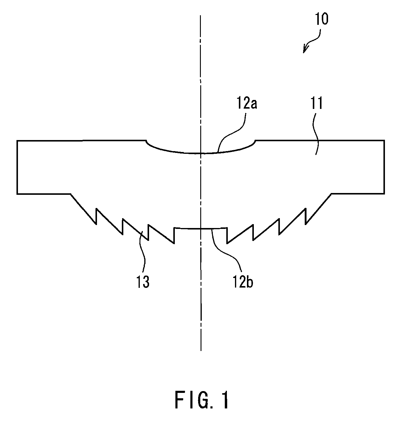
[0052]FIG. 1 is a cross-sectional view of a diffractive imaging lens according to the present embodiment. A diffractive imaging lens 10 is a single lens. A first surface 12a of a substrate 11 of the lens is aspherical. A second surface 12b opposed thereto is an aspherical surface on which a ring-shaped diffraction grating pattern 13 is formed. The first surface and the second surface refer to a surface on the subject side and a surface on the image formation side, respectively, of both surfaces of the lens. Respective ring pitches of the diffraction grating pattern 13 are arranged at irregular intervals. In the figure, steps of the diffraction grating pattern and the shape of the lens are shown schematically in favor of visibility.

[0053]The substrate 11 is made of ZEONEX480R (with a d-line refractive index of 1.5247 and an Abbe number of 56.2) produced by Zeon Corporation. The lens has a thickness of 0.65 mm on an optical axis.

[0054]Table 1 below shows aspherical coefficients of the...

embodiment 2

[0100]Hereinafter, a diffractive imaging lens according to Embodiment 2 of the present invention will be described. Descriptions will be omitted as to duplication of Embodiment 1 as described above. FIG. 4 is a cross-sectional view of the diffractive imaging lens according to the present embodiment. A diffractive imaging lens 40 is a single lens.

[0101]On a first surface 42a of a substrate 41, a ring-shaped diffraction grating pattern 43a is formed on an aspherical surface. Further, a protective film 44a is provided so as to cover the diffraction grating pattern 43a. On a second surface 42b opposed to the first surface 42a, a ring-shaped diffraction grating pattern 43b is formed on an aspherical surface. Further, a protective film 44b is provided so as to cover the diffraction grating pattern 43b. The protective films 44a and 44b are applied so that the underlying aspherical shapes are reflected on their surfaces. In the figure, steps of the diffraction grating patterns and the shape...

embodiment 3

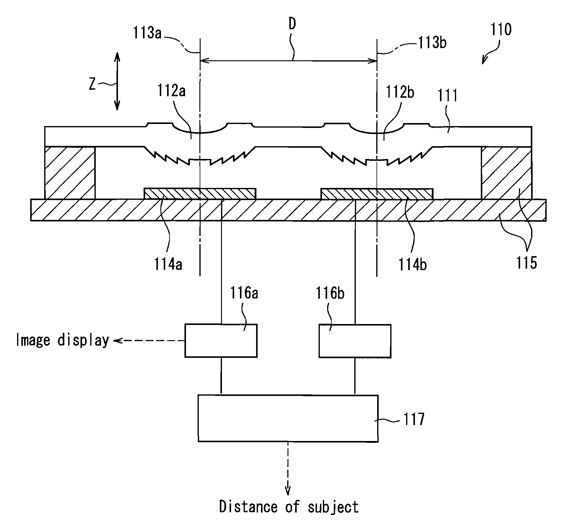
[0155]FIG. 11 is a cross-sectional view of an imaging apparatus according to an embodiment of the present invention, taken along an optical axis. An imaging apparatus 110 is a compound-eye type imaging apparatus having a plurality of units, each including a diffractive imaging lens optical system with a diffractive imaging lens and a solid-state imaging device. Two lenses 112a and 112b are integrated in a lens array 111. The two lenses 112a and 112b each are a double-sided aspherical single lens independent of each another, and include a diffraction grating pattern formed only on one side. Each of these lenses corresponds to the diffractive imaging lens according to Embodiment 1. Each of these diffractive imaging lenses is combined with a diaphragm (not shown), so that the diffractive imaging lens optical system is configured.

[0156]An optical axis 113a of the lens 112a and an optical axis 113b of the lens 112b are parallel to each other. As shown in FIG. 11, Z represents a direction...


PUM

PropertyMeasurementUnit
Lengthaaaaaaaaaa
Lengthaaaaaaaaaa
Lengthaaaaaaaaaa

Abstract

A diffractive imaging lens 10 includes a surface on which a diffraction grating pattern is formed. The diffraction grating pattern is formed of a plurality of steps formed concentrically with an optical axis (25) at a center. The diffraction grating pattern is formed such that a first portion where amounts (di) of the steps are substantially the same in a radial direction of concentric circles and a second portion, outside of the first portion, where amounts (di) of the steps decrease with distance from the optical axis 25 are provided, or such that the amounts (di) of the steps decrease with distance from the optical axis 25 over the entire diffraction grating pattern.

Description

TECHNICAL FIELD[0001]The present invention relates to a diffractive imaging lens provided with a diffraction grating pattern, a diffractive imaging lens optical system, and an imaging apparatus using the diffractive imaging lens optical system.BACKGROUND ART[0002]Camera modules for forming an image of a subject on a solid-state imaging device via a lens system are used widely for digital still cameras and mobile phone cameras. In recent years, camera modules have been required to have a larger number of pixels in combination with a lower profile. In general, as the number of pixels is increased, a lens system is required to have a higher resolution. Therefore, the thickness of a camera module tends to increase in the optical axis direction.[0003]In this regard, when a pixel pitch of a solid-state imaging device is reduced, it is possible to reduce the imaging apparatus in size while keeping the same number of pixels. Based on this, an attempt has been made to enable the downsizing o...

Claims


Application Information

Patent Timeline
IPC IPC(8): H04N5/225G02B5/18G02B1/10G02B27/44G02B1/04G02B13/00G02B13/18
CPCG02B3/0068G02B3/0075G02B27/4272G02B27/4216G02B3/08
Inventor KORENAGA, TSUGUHIROANDO, TAKAMASASUZUKI, MASA-AKI
Owner PANASONIC CORP
Why Eureka
Try Eureka