

Optical scanning apparatus
a scanning apparatus and optical box technology, applied in the direction of electrographic process apparatus, instruments, printing, etc., can solve the problems of deformation of optical boxes, difficulty in dust entering the apparatus,
- Summary
- Abstract
- Description
- Claims
- Application Information
AI Technical Summary
Benefits of technology
Problems solved by technology
Method used
Image

Examples
embodiment 1
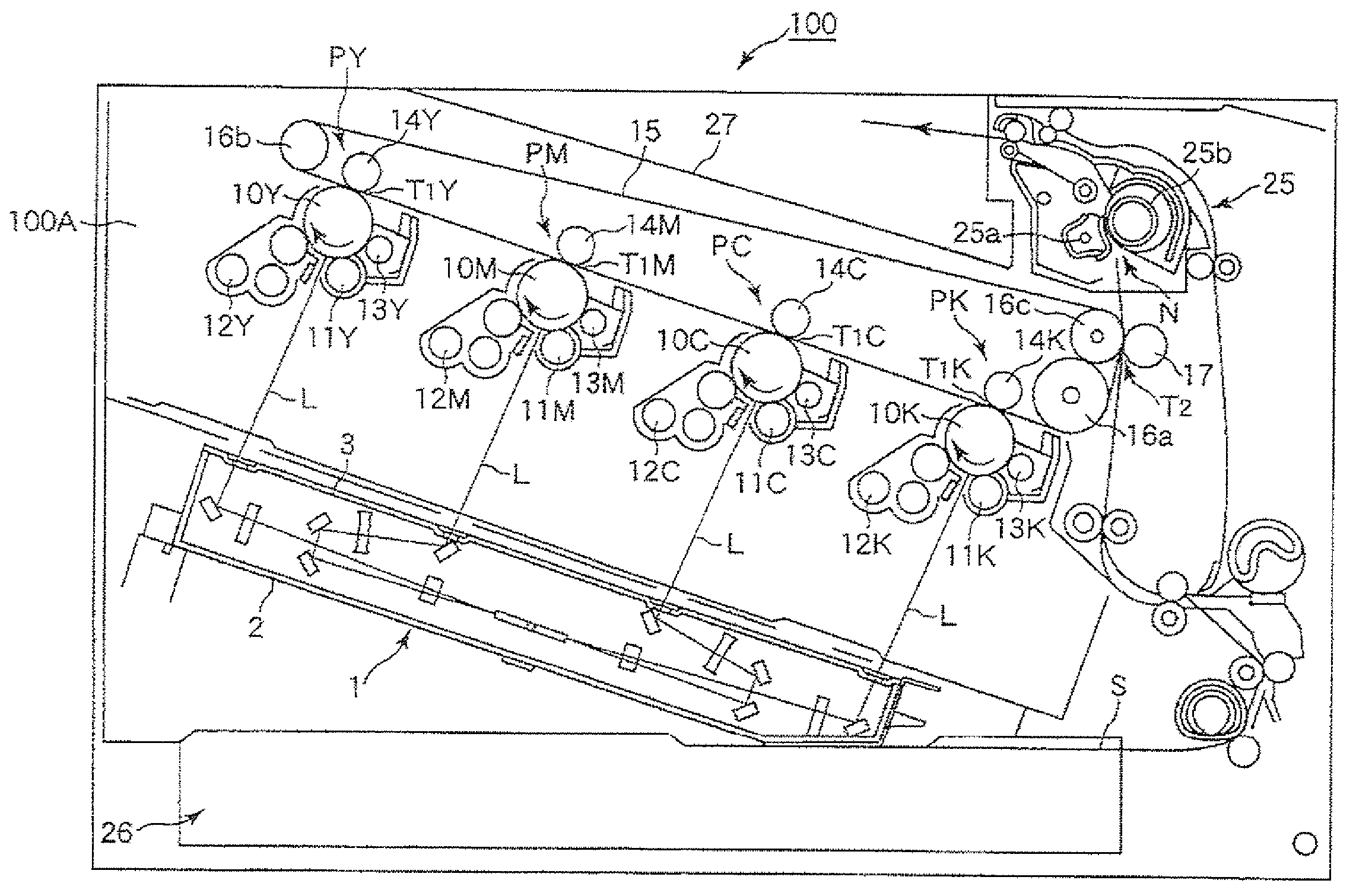
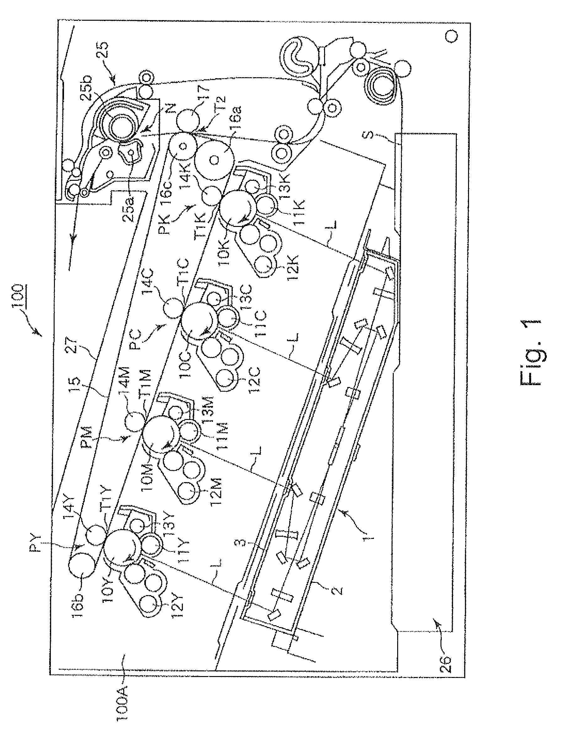
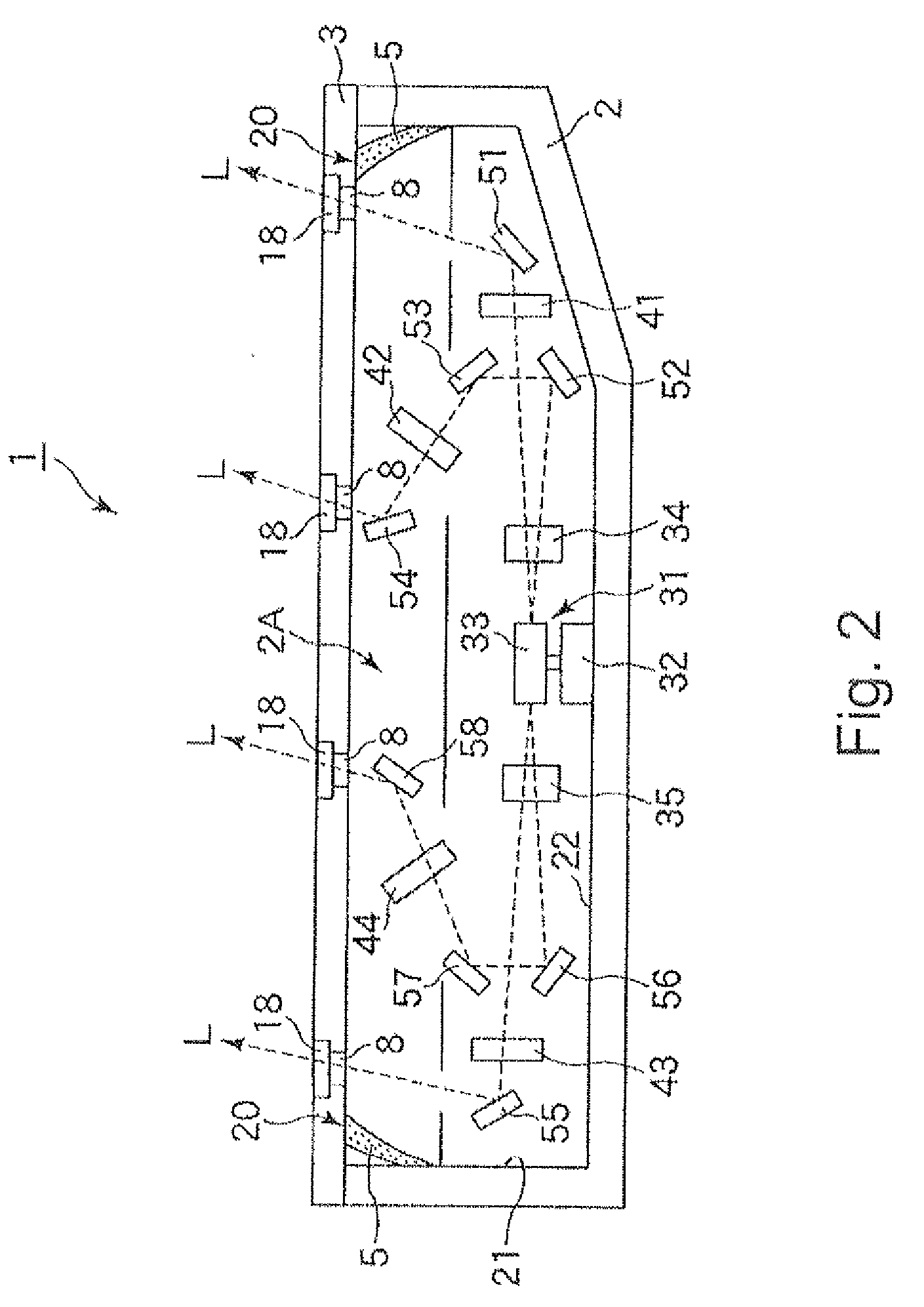
[0026]FIG. 1 is a sectional view of an electrophotographic full-color printer, as an example of an image forming apparatus, in which the optical scanning apparatus in accordance with the present invention is mountable. It shows the general structure of the image forming apparatus. FIG. 2 is a sectional view of the optical scanning apparatus in this preferred embodiment of the present invention. It shows the general structure of the apparatus. (General Structure of Image Forming Apparatus)
[0027]First, referring to FIG. 1, the electrophotographic full-color printer, as an example of an image forming apparatus, in which the optical scanning apparatus in accordance with the present invention is mountable, will be described. The image forming apparatus 100 in this embodiment is of a so-called tandem type. It has four image forming portions (PY, PM, PC, and PK), which are disposed in tandem in a straight line.
[0028]The image forming apparatus has: an image forming portion PY, which is for...
embodiment 2
[0096]This preferred embodiment of the present invention will be described primarily regarding the problem which might occur when assembling the optical scanning apparatus 1, based on the contents of the description of the first preferred embodiment of the present invention given above.
[0097]The abovementioned problem that when the lid 3, to which the sealing member 5 formed of thermoplastic elastomer has been attached, is attached to the optical box 2 of the optical scanning apparatus 1, dusts or the like contaminants enter the optical box. Thus, hereafter, the means for preventing the dusts or the like from entering the optical box (optical scanning apparatus) will be described along with this problem.
[0098]It is sometimes noticed, during the process of attaching the lid 3 to the optical box 2, that after the formation of the sealing member 5 on the lid 3 in a manner to be integrated with the lid 3, fine dusts have adhered to the integral combination of the sealing member 5 and li...
embodiment 3
[0117]Referring to FIGS. 13A, 13B and 13C, a further embodiment of the present invention will be described. FIG. 13A is a sectional view of a part of a cap 3 and a different bent type sealing member 131. FIG. 13B is a partial perspective view of the bent type sealing member 131. FIG. 13C is a partially sectional view illustrating a state in which the bent type sealing member 131 is in contact with the inner wall 21 (side wall 21) of the optical box. The broken line 21a shows a surface of the wall when the inner wall 21 is offset inwardly.
[0118]The bent type sealing member 131 of this embodiment is produced, similarly to the first embodiment, by the insertion molding with a thermoplastic elastomer, wherein the sealing member 131 has a material and rigidity which are different from those of the cap 3, similarly. The bent type sealing member 131 of this embodiment is different from the first embodiment in the sealing material and the cross-sectional configuration. As shown in FIG. 13A,...
PUM
 Abstract
Description
Claims
Application Information