Integrated laser cleaning photoelectric system

A laser cleaning and optoelectronic system technology, applied in the field of laser cleaning, can solve the problems that the laser cleaning terminal equipment cannot realize online monitoring, and cannot be used for precision cleaning, etc., to achieve high-precision and high-efficiency laser cleaning, and achieve the effect of precise control

Pending Publication Date: 2018-11-02
深圳市汇泽激光科技有限公司
View PDF12 Cites 10 Cited by
  • Summary
  • Abstract
  • Description
  • Claims
  • Application Information

AI Technical Summary

Problems solved by technology

[0004] The purpose of the present invention is to provide an integrated laser cleaning photoelectric system, which solves the problem that the laser cleaning terminal equipment in the prior art cannot realize the online monitoring and online detection functions and cannot be applied to the situation requiring precision cleaning

Method used


Image

  • Integrated laser cleaning photoelectric system
  • Integrated laser cleaning photoelectric system

Examples


Embodiment 1

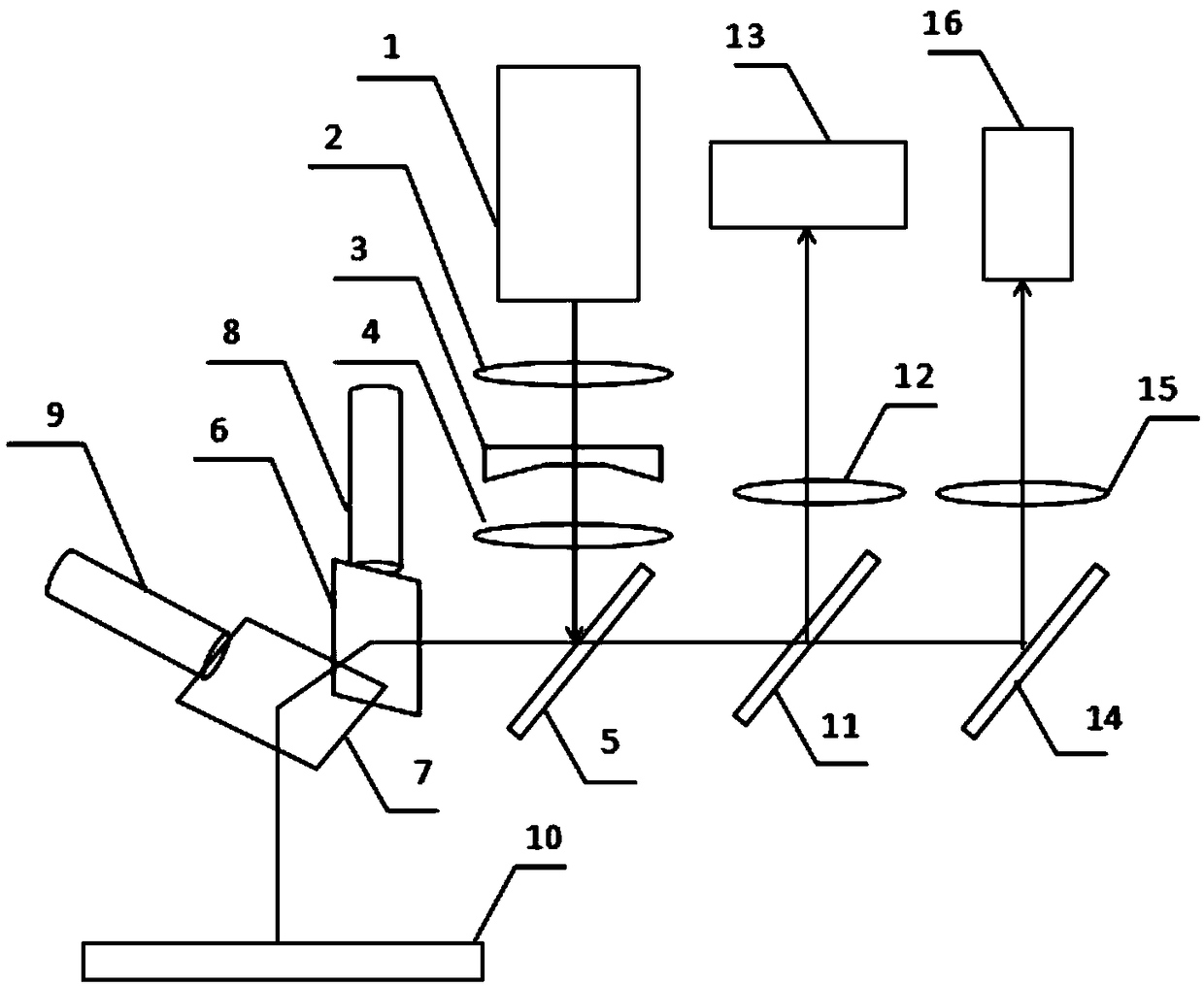
[0030] Such as figure 1 As shown, the collimating beam expanding optical assembly is located above the first optical mirror body 5, and the laser 1 is located above the collimating beam expanding optical assembly. The online monitoring component is located above the second optical mirror body 11 , and the spectrum analysis component is located above the third optical mirror body 14 . Specifically, the laser 1, the collimating lens 2, the concave lens 3, the convex lens 4 and the first optical mirror body 5 are on the same straight line; Above, high-speed camera 13, imaging lens 12 and second optical mirror body 11 are on the same straight line; The collection lens 15 and the third optical mirror body 14 are on the same straight line.

[0031] Among them, the laser 1 can be a solid-state or fiber laser, and can be a pulsed or continuous output laser, outputting a fundamental frequency 1064nm laser beam or a 532nm laser beam, and the direction of the laser beam emitted by the ...

Embodiment 2

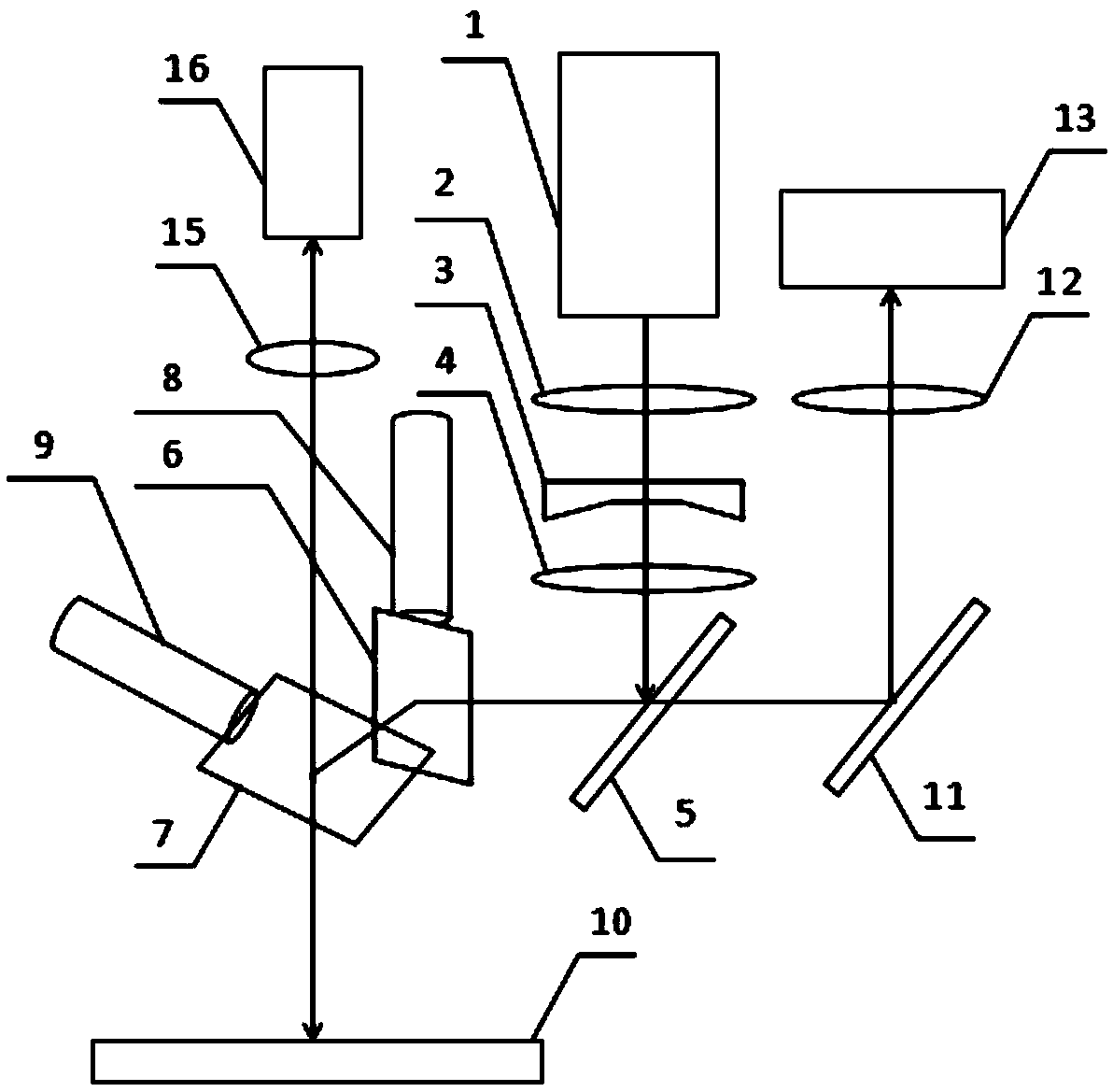
[0041] The difference with embodiment 1 is: as figure 2 As shown, the spectral analysis component is placed directly above the X-axis scanning galvanometer 7 , that is, the spectrum collection lens 15 is located directly above the X-axis scanning galvanometer 7 , and the spectrometer 16 is located directly above the spectrum collection lens 15 . At this time, the X-axis scanning galvanometer 7 is not only coated with an ultraviolet-enhanced aluminum film on the reflective surface, which can have a high reflectivity for the spectral signal in the 200nm-1100nm band, and the X-axis scanning galvanometer 7 is a half-transparent half-reflective mirror , has transflective properties in the 400nm-800nm ​​band, so as to ensure that a part of the 400nm-800nm ​​light wave signal can be transmitted, the X-axis scanning galvanometer 7 is incident on the surface of the spectrum collection lens 15, and then is focused by the spectrum collection lens 15 to the spectrometer 16 . At this tim...


PUM


Abstract

The invention relates to an integrated laser cleaning photoelectric system. The system comprises a laser device used for emitting a laser beam for cleaning, an online monitoring assembly used for monitoring the laser cleaning process online, a spectral analysis assembly used for analyzing product components in the laser cleaning process, and an optical assembly used for guiding the laser beam of the laser device to be emitted to the surface of a to-be-cleaned sample. The optical assembly can simultaneously guide spectral signals radiated outwards from the surface of the to-be-cleaned sample tobe emitted to the online monitoring assembly and the spectral analysis assembly. The integrated laser cleaning photoelectric system can be used for online monitoring of the laser cleaning process andonline analysis of additional products, so that accurate control over the laser cleaning process is achieved, and the purpose of high-precision and high-efficiency laser cleaning is achieved.

Description

technical field [0001] The invention relates to the technical field of laser cleaning, and more specifically relates to an integrated laser cleaning photoelectric system. Background technique [0002] Traditional cleaning methods are mainly divided into chemical and mechanical cleaning methods, both of which will cause serious secondary pollution to the environment and personnel. As a clean cleaning method, laser cleaning is gradually becoming known to people. It uses laser beams as the cleaning medium, and utilizes the high energy density and pulse characteristics of the laser to form extremely high temperature and thermal shock on the surface of the material to be removed. Due to the huge temperature difference between the matrix material and the surface removal material, different thermal expansion effects will be produced. With the assistance of thermal shock, the rapid peeling of the surface material and the matrix material can be achieved, and the high energy density o...

Claims


Application Information

Patent Timeline
Patent Type & Authority Applications(China)
IPC IPC(8): B08B7/00G01N21/31
CPCG01N21/31B08B7/0042
Inventor 谢曦宇郑重辜毓净张兴斌邓松辉
Owner 深圳市汇泽激光科技有限公司
Why Eureka
Try Eureka