Surface light source device and liquid crystal display device

a technology of liquid crystal display and light source device, which is applied in the direction of lighting and heating apparatus, mechanical equipment, instruments, etc., can solve the problems of reduced light transmission through color filter, reduced luminance, and extremely reduced quantity of transmitted light, and achieves simple structure and high quality

Active Publication Date: 2016-02-25
MITSUBISHI ELECTRIC CORP
View PDF3 Cites 10 Cited by
  • Summary
  • Abstract
  • Description
  • Claims
  • Application Information

AI Technical Summary

Benefits of technology

The present invention provides a surface light source device and a liquid crystal display device that can display an image of high quality with a simple structure when simultaneously using two types of light sources having different light emission characteristics from each other. This is achieved by converting the first and second light emitted from the different light sources into linear light, and then distributing and mixing them through reflection and diffusion to achieve a uniform and high-quality illumination. This invention increases the utilization efficiency of the light and simplifies the display structure, allowing for a high-quality image to be displayed.

Problems solved by technology

For this reason, if the color purity of the display color is to be increased, there is a problem in that a quantity of light transmitted through the color filter is decreased, resulting in reduction in a luminance.
If the color purity is to be increased in a wavelength region of 630 to 640 nm which is preferable as pure red in the red color, therefore, there is a problem in that the quantity of transmitted light is extremely reduced, resulting in significant reduction in a luminance.
However, the laser is a light source having a very small divergence angle, and is difficult to have equivalent expansion to LED light with a large divergence angle by a lens and the light emitting diode device through the same method as the LED.
When distribution of a laser beam is different from that of the LED light over a display surface, luminance unevenness and color irregularity are caused.
It is difficult to create a uniform surface light source with the same structure.
When two types of light sources are each caused to have structures for creating surface light sources, moreover, the structures are made complicated so that a manufacturing cost is increased.

Method used


Image

  • Surface light source device and liquid crystal display device
  • Surface light source device and liquid crystal display device
  • Surface light source device and liquid crystal display device

Examples


first preferred embodiment

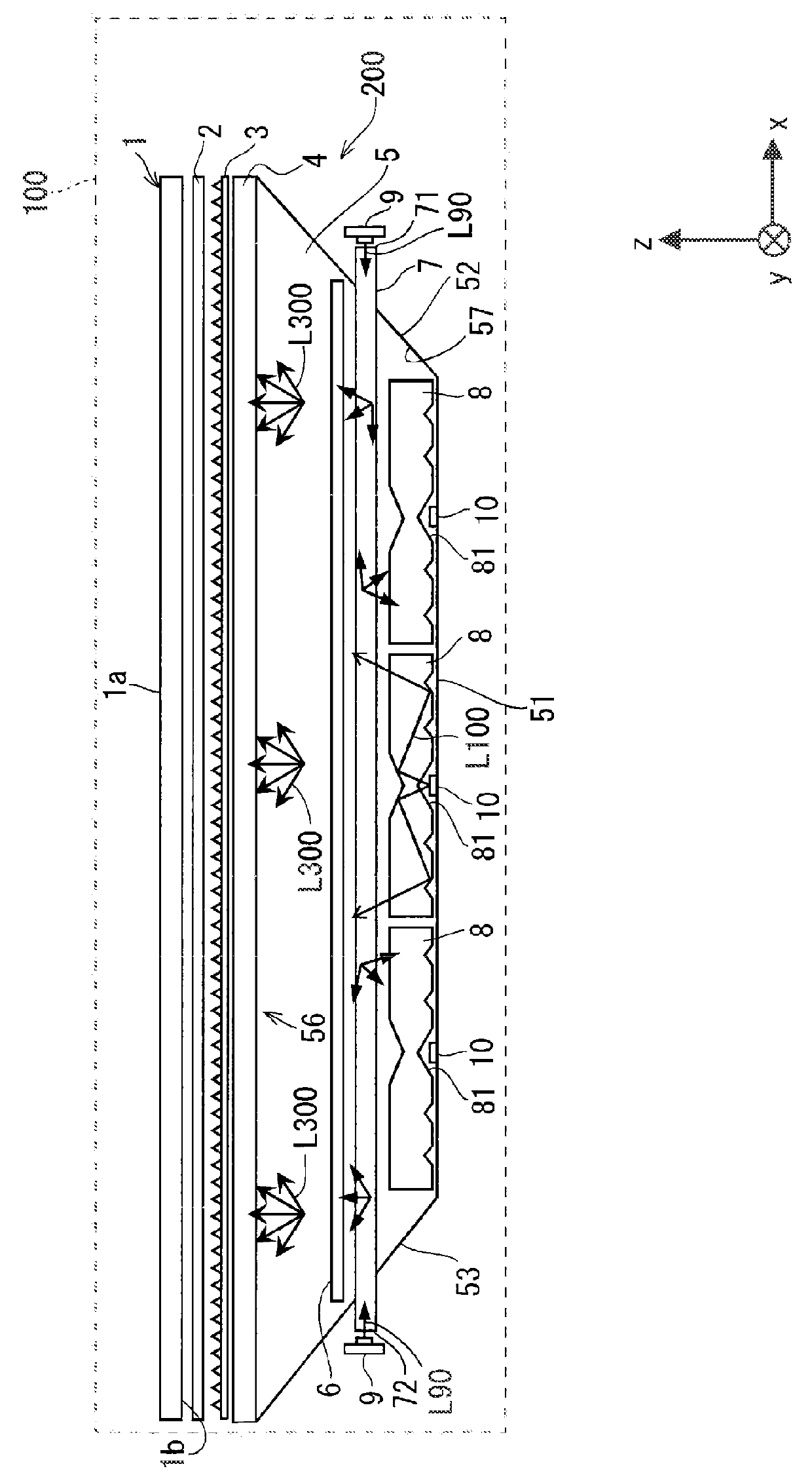
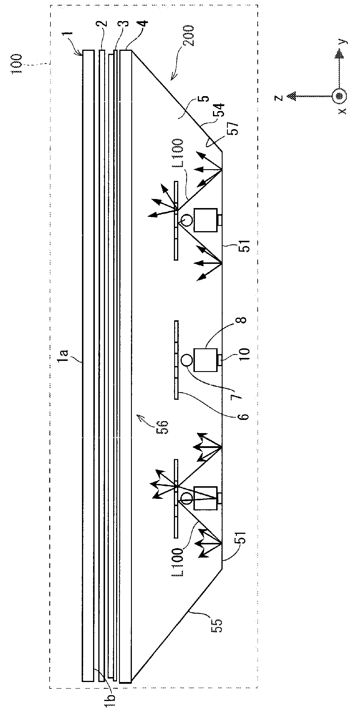
[0036]A first preferred embodiment according to the present invention will be described below with reference to the drawings. FIG. 1 is a view schematically showing an example of a structure of a liquid crystal display device 100 according to the first preferred embodiment, FIG. 2 is a view schematically showing an example of a structure of a surface light source device 200, and FIG. 3 is a view schematically showing an example of the structure of the liquid crystal display device 100.

[0037]As shown in FIG. 1, the liquid crystal display device 100 includes a transmission type liquid crystal panel 1 formed of a liquid crystal display element, an optical sheet 2, an optical sheet 3, and the surface light source device 200. Moreover, although not illustrated in FIG. 1, the liquid crystal display device 100 further includes a control unit 31, a liquid crystal panel driving unit 32, an LED light source driving unit 33a, and a laser beam source driving unit 33b as shown in FIG. 4. The det...

second preferred embodiment

[0119]Next, a liquid crystal display device and a surface light source device according to a second preferred embodiment will be described. FIG. 13 is a configuration view schematically showing an example of a reflecting bar 16 of the surface light source device according to the second preferred embodiment. In the second preferred embodiment, explanation of the same components as those described in the first preferred embodiment will be omitted.

[0120]In the second preferred embodiment, a structure of the reflecting bar 16 is different from that of the reflecting bar 6 according to the first preferred embodiment. The reflecting bar 16 has a reflecting portion 161, a diffusion reflecting portion 162, a reflecting portion 163, and a diffusion reflecting portion 164 provided in order from a central part to an end in a short direction. The reflecting portion 161, the diffusion reflecting portion 162, and the reflecting portion 163 have the same functions as the reflecting portions 61 and...


PUM


Abstract

A surface light source device includes a laser beam source, a laser beam guide rod for converting a laser beam into first linear light, an LED light source, an LED light guide rod for converting LED light into second linear light, a reflecting bar having a reflecting portion for reflecting part of the first and second linear light and a diffusion reflecting portion for diffusing and reflecting a residual part of the first and second linear light, and a light reflecting portion formed in a box shape and having an opening portion with an emission side opened and a reflecting surface on an inside of the box shape. Part of the first and second linear light is reflected by the reflecting portion and the reflecting surface, and a residual part is diffused and reflected by the diffusion reflecting portion and is emitted from the opening portion.

Description

BACKGROUND OF THE INVENTION[0001]1. Field of the Invention[0002]The present invention relates to a surface light source device for illuminating a back surface of a liquid crystal display element by two types of light sources having different characteristics, thereby displaying an image on the liquid crystal display element, and a liquid crystal display device including the surface light source device.[0003]2. Description of the Background Art[0004]A liquid crystal display element provided in a liquid crystal display device does not emit light by itself. For this reason, the liquid crystal display device includes a backlight device (a surface light source device) as a light source for illuminating the liquid crystal display element at a back surface side of the liquid crystal display element.[0005]Moreover, the liquid crystal display element includes a color filter and transmits, through a color filter, only light having a part of wavelengths in light emitted from a fluorescent lamp ...

Claims


Application Information

Patent Timeline
IPC IPC(8): F21V8/00G02F1/1335
CPCG02B6/0055G02B6/0068G02B6/0088G02F2001/133626G02F1/133524G02F1/133602G02B6/0051G02F1/133615G02F1/133607G02B6/0073G02F1/133603G02F1/133609
Inventor OKIMOTO, NAMIMAEDA, SAKINLLKURA, EIJIDAIJOGO, AKIRAYAMAMOTO, TAKESHI
Owner MITSUBISHI ELECTRIC CORP
Why Eureka
Try Eureka