Powder pressing method and apparatus based on laser shock wave technology

A shock wave and powder technology, applied in laser welding equipment, manufacturing tools, welding equipment, etc., can solve the problems of difficult control of explosion parameters, poor explosion suppression safety, and rupture of the blank core, and achieve the effect of avoiding the rupture of the blank core.

A shock wave and powder technology, applied in laser welding equipment, manufacturing tools, welding equipment, etc., can solve the problems of difficult control of explosion parameters, poor explosion suppression safety, and rupture of the blank core, and achieve the effect of avoiding the rupture of the blank core.

CN1772420AInactive Publication Date: 2006-05-17JIANGSU UNIV

Image

  • Powder pressing method and apparatus based on laser shock wave technology
  • Powder pressing method and apparatus based on laser shock wave technology

Examples


Embodiment Construction

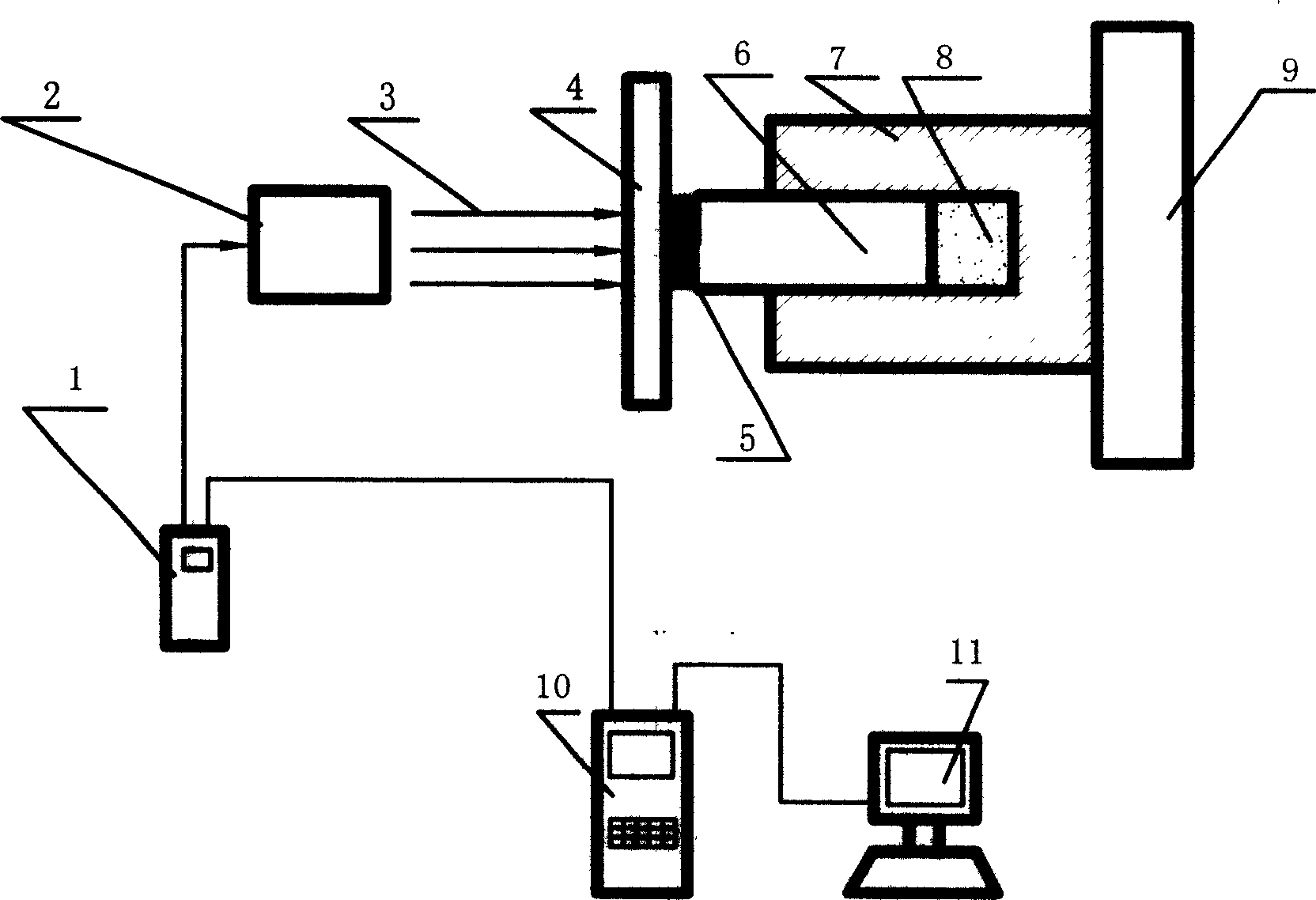
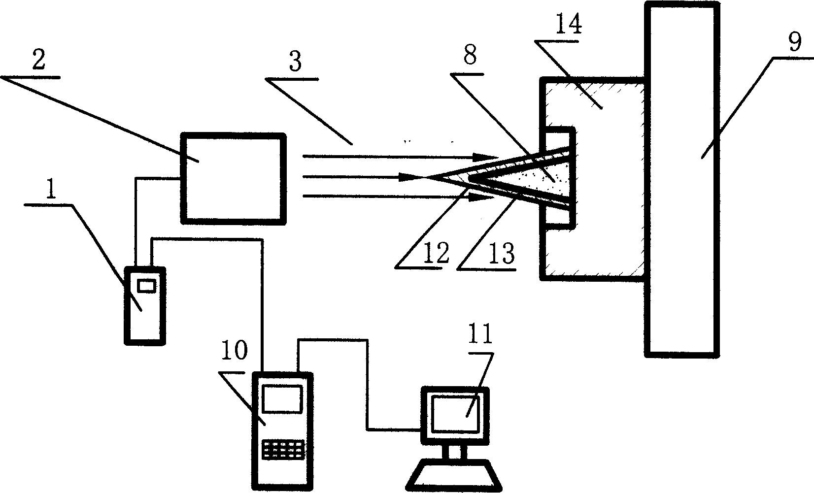
[0022] The details and working conditions of the specific device proposed by the present invention will be described in detail below in conjunction with the accompanying drawings.

[0023] The device for powder compaction by this method comprises a laser generator control device 1, a laser generator 2, a workbench 9 and a powder mold system. Among them, the powder mold system is divided into an indirect compression molding powder mold system and a direct compression molding powder mold system. The indirect compression molding powder mold system is composed of constraining layer 4 , absorbing layer material 5 , piston 6 , mold 7 and powder 8 . The direct compression forming powder mold system is composed of an absorbent layer material 12 mixed with explosives, a metal thin-walled shell 13 , a base 14 and powder 8 .

[0024] The laser generator generates laser pulses with an energy of 10-100 joules and a duration of 8-80 nanoseconds. The spot mode of the laser beam 3 can be a f...


PUM


Abstract

The present invention relates to powder metallurgy technology, and is especially powder pressing method and apparatus based on laser shock wave technology. The present invention is especially suitable for pressing small size irregular samples. The apparatus of the present invention consists of laser, laser beam guiding system, laser controller, restricting layer and absorption layer material, powder metallurgical mold system and work table. Owing to the precise control of the laser parameters and the capacity of repeated loading, the present invention can meet the requirement of pressing samples of different density.

Description

technical field [0001] The invention relates to the field of powder metallurgy, in particular to a powder pressing method and device based on laser shock wave technology, and is especially suitable for pressing and forming small irregular test pieces. Background technique [0002] The traditional powder compaction method in powder metallurgy is mechanical compaction, that is, the powder is filled in the mold, and then the pressure is applied to the piston by a pressure machine, and the powder in the mold is pressed into shape by the extrusion of the piston. This method not only requires special pressure equipment, but also the porosity of the pressed test piece is large, and it is difficult to press and form some irregularly shaped test pieces. [0003] The technology closest to the present invention is the explosive powder compaction technology. Explosion suppression is to use the shock wave generated by the explosion of explosives to press the powder into shape. This met...

Claims


Application Information

Patent Timeline
17 May 2006
Publication
CN1772420A
IPC
B22F3/087
CPC
B23K26/356
Inventors
张永康; 顾永玉