Fan and fan frame thereof

a fan and fan frame technology, applied in the direction of machines/engines, stators, liquid fuel engines, etc., can solve the problems of large difference between airflow speeds, electronic products may be burnt out, performance deterioration, etc., to improve the fan characteristics, reduce the interference of turbulence, and increase the air volume and air pressure

Active Publication Date: 2009-09-10
DELTA ELECTRONICS INC
View PDF13 Cites 24 Cited by
  • Summary
  • Abstract
  • Description
  • Claims
  • Application Information

AI Technical Summary

Benefits of technology

[0007]In view of the foregoing, the present invention is to provide a fan and a fan frame thereof that have the integrated design of the main body and the base so as to improve the performance of the fan and increase air volume and air pressure. In addition, the present invention can prevent the turbulence occurred at the outlet of the fan so as to decrease the noise.
[0011]As mentioned above, the fan and fan frame of the present invention have the integrated design of the base and the main body, so that the distance between the outer surface of the base and the inner surface of the main body can be uniform. Thus, the airflow field through the outlet can be kept steady so as to reduce the interference of the turbulence. Also, the design of the present invention allows the airflow to flow through the slant plane of the hub and then sequentially through the inclined plane of the base, thereby achieving the effect of continuously pressing. Compared with the conventional fans, the present invention not only improves the fan characteristics and increases the air volume and air pressure for the fan, but also prevents the turbulence generated at the outlet so as to decrease the noise.

Problems solved by technology

If the heat generated by the electronic product can not be dissipated properly, the performance may deteriorate and, even worse, the electronic product may be burnt out.
That is, parts of the guiding angles R disposed at the side edges of the square structure will form several straight-cut lines P. In this case, the distance between the base 12 and the straight-cut line P is different from that between the base 12 and the guiding angle R. Thus, the variation of the area of the outlet S is too large, which may result in the large difference between the airflow speeds at the outlet S. This will cause the turbulence of the airflow at the outlet S and thus increase the noise.

Method used


Image

  • Fan and fan frame thereof
  • Fan and fan frame thereof
  • Fan and fan frame thereof

Examples


Embodiment Construction

[0021]The present invention will be apparent from the following detailed description, which proceeds with reference to the accompanying drawings, wherein the same references relate to the same elements.

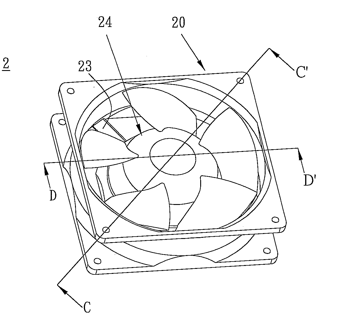
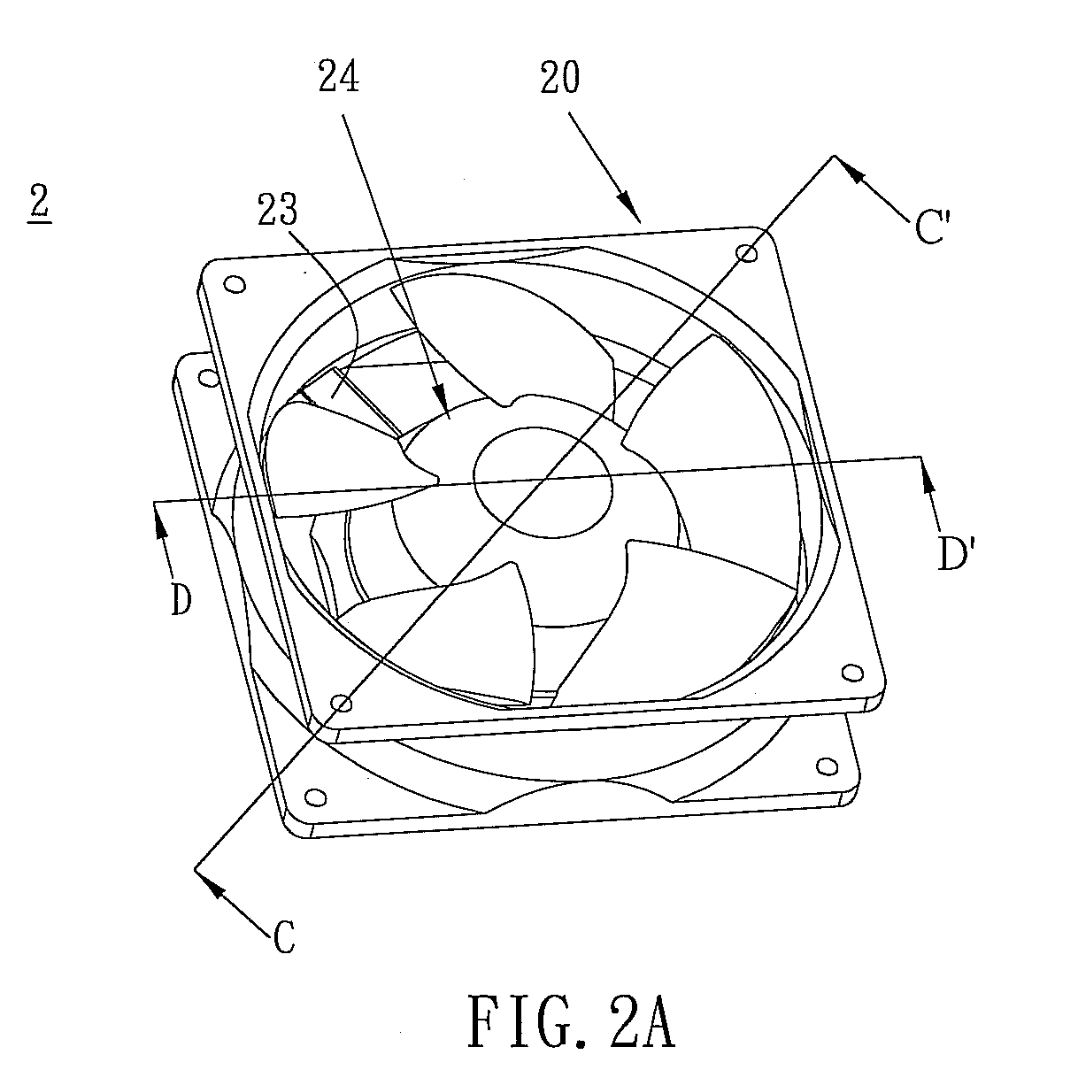
[0022]FIG. 2A is a schematic illustration showing a fan according to the preferred embodiment of the present invention, and FIG. 2B is a cross sectional view of the fan in FIG. 2A along line CC′. With reference to FIGS. 2A and 2B, a fan 2 includes a fan frame 20, an impeller 24 and a motor 25. In the embodiment, the fan 2 is, for example but not limited to, an axial-flow fan. The fan frame 20 includes a main body 21 and a base 22. The main body 21 can have a square, rectangular or elliptic shape, which is designed according to the actual needs. In the embodiment, the shape of the main body 21 is square.

[0023]The base 22 is disposed in the main body 21. The fan frame 20 further includes a plurality of connecting members 23 disposed between the main body 21 and the base 22 for connectin...


PUM


Abstract

A fan includes a fan frame and an impeller. The fan frame includes a frame body and a base, and the impeller is accommodated in the main body and is disposed on the base. The frame body has a column-shaped passage, an airflow outlet and an airflow inlet. The main body further has two expansion portions respectively disposed adjacent to the outlet and inlet. The expansion portions extend from the column-shaped passage to the outlet and the inlet, respectively. The main body has at least two planar sides so as to allow parts of the expansion portions to respectively form straight-cut lines where the planar sides are located, respectively. The base has several straight-cut planes, and each of the straight-cut planes is located with respect to the straight-cut line.

Description

CROSS REFERENCE TO RELATED APPLICATIONS[0001]This Non-provisional application claims priority under 35 U.S.C. §119(a) on Patent Application No(s). 097108186, filed in Taiwan, Republic of China on Mar. 7, 2008, the entire contents of which are hereby incorporated by reference.BACKGROUND OF THE INVENTION[0002]1. Field of Invention[0003]The present invention relates to a fan and a fan frame.[0004]2. Related Art[0005]Since the performances of electronic products have been improved, a heat dissipation device becomes one of the indispensable equipments for the electronic products. If the heat generated by the electronic product can not be dissipated properly, the performance may deteriorate and, even worse, the electronic product may be burnt out. Especially for the micro electronic devices such as the integrated circuits (ICs), the dissipation device is much more important. Because the integrated density of the ICs increases and the packaging technology progresses, the size of the ICs be...

Claims


Application Information

Patent Timeline
Patent Type & Authority Applications(United States)
IPC IPC(8): F04D29/54
CPCF04D25/0613F04D29/541F04D29/526
Inventor LIU, WEN-BINHSU, SHUO-SHIUCHANG, SHUN-CHEN
Owner DELTA ELECTRONICS INC
Why Eureka
Try Eureka