Stretch Composite Fabric and Expanded Porous Polytetrafluoroethylene Film

a technology of stretch composite fabric and porous polytetrafluoroethylene, which is applied in the direction of knitting, weaving, straight-bar knitting machines, etc., can solve the problems of lack of cohesive strength at the region, likely delamination phenomenon, and lack of cohesive strength of a surface without stretch resin application, so as to increase the strength and stretch property of the eptfe film

a technology of stretch composite fabric and porous polytetrafluoroethylene, which is applied in the direction of knitting, weaving, straight-bar knitting machines, etc., can solve the problems of lack of cohesive strength at the region, likely delamination phenomenon, and lack of cohesive strength of a surface without stretch resin application, so as to increase the strength and stretch property of the eptfe film

US20090227165A1Inactive Publication Date: 2009-09-10JAPAN GORE TEX INC

Image

  • Stretch Composite Fabric and Expanded Porous Polytetrafluoroethylene Film
  • Stretch Composite Fabric and Expanded Porous Polytetrafluoroethylene Film
  • Stretch Composite Fabric and Expanded Porous Polytetrafluoroethylene Film

Examples


example 1

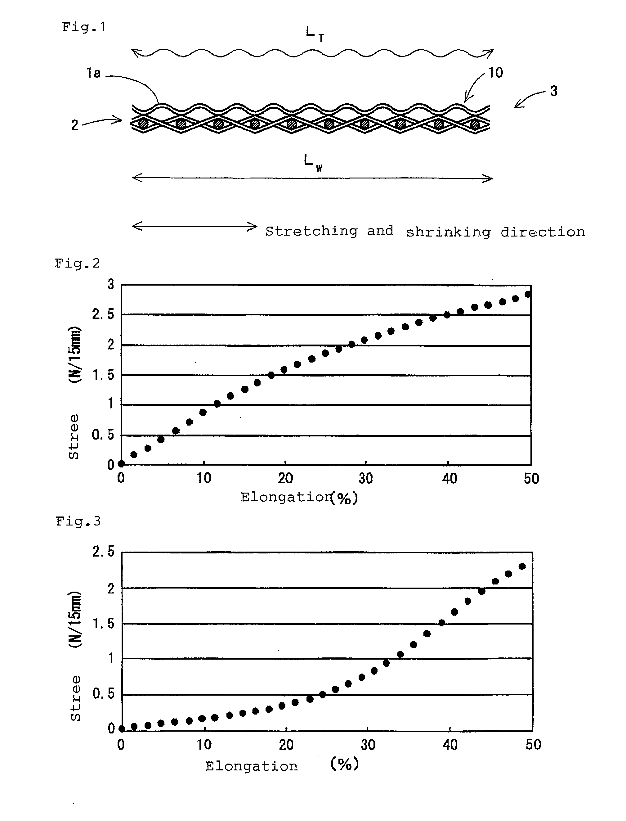
[0081]To a device equipped with a tenter for extending the width in a heater oven (hereinafter referred to as Device A), a sintered ePTFE film (thickness: 50 μm, maximum pore size: 0.3 μm, porosity: 80%, mass per unit area: 22 g / m2, breaking elongation in a width direction in a tensile test: 260%) manufactured by Japan Gore-Tex Inc. was continuously fed, and the film was stretched in a width direction by the tenter. The film was shrunk by reducing the width of the tenter to 1.05 times the original width thereof in the oven, and the film was removed from the tenter and continuously taken up (the detailed stretching and shrinking conditions are as described in the following Tables 1 and 2). At this time, in order to prevent the occurrence of film necking in a length direction, the film was allowed to travel at an appropriate rate.

[0082]The tensile stress at 10% elongation of the sintered ePTFE film before and after the stretching and shrinking treatments is shown in the following Tabl...

reference example 1

[0083]The same procedure as in Example 1 was performed except that the stretching temperature was changed to room temperature (around 25° C.). The film was torn during stretching, and the stretching treatment could not at all be performed.

example 2

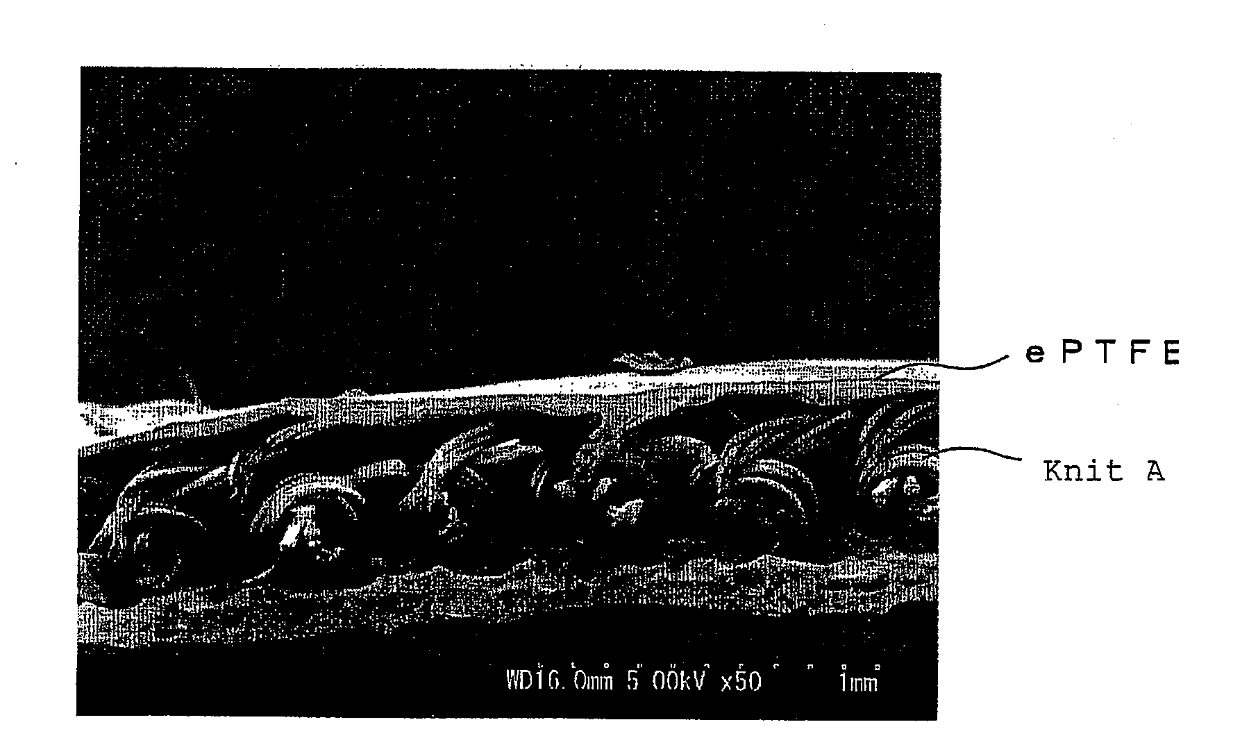
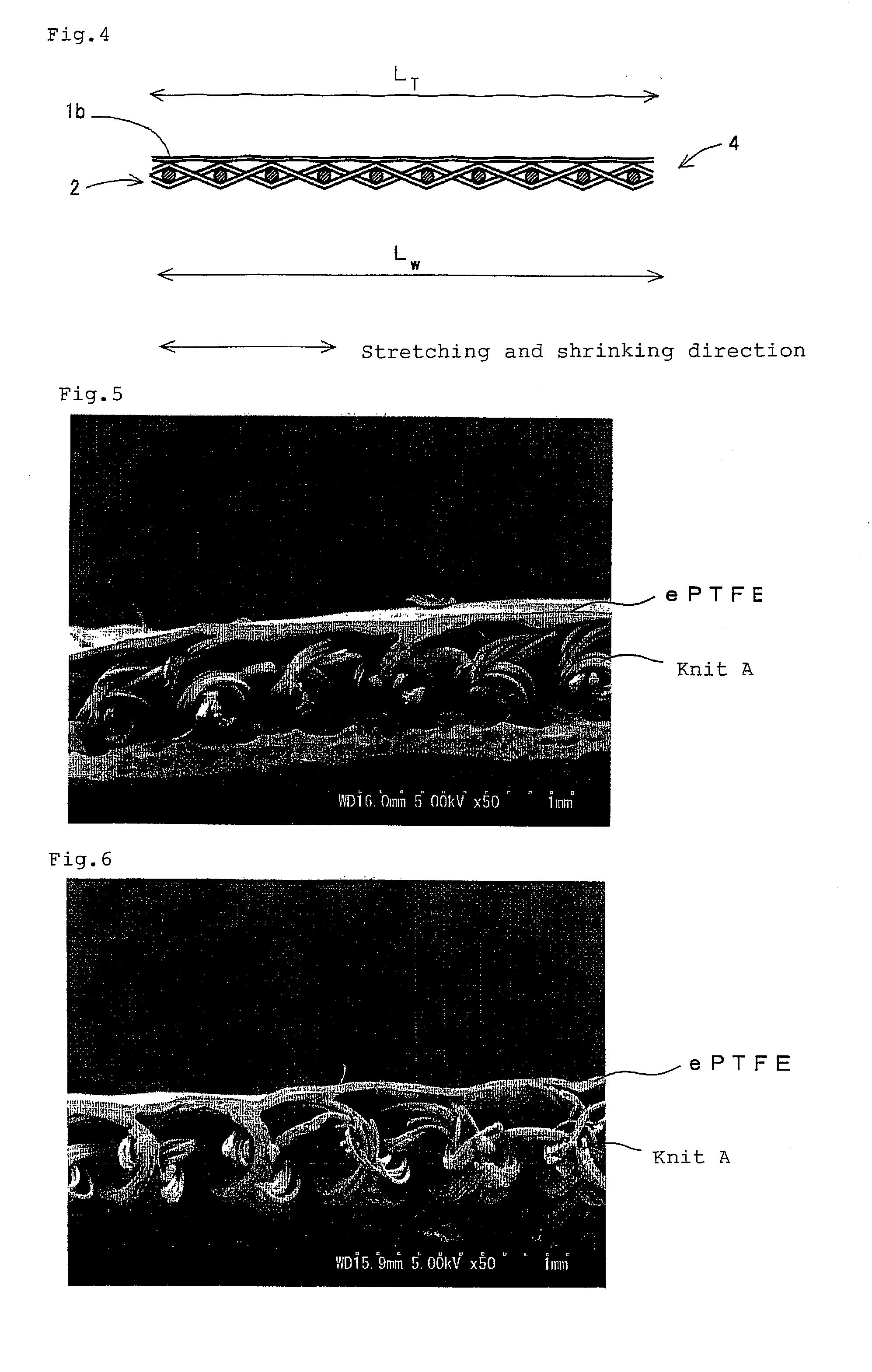
[0084]To one surface of the sintered ePTFE film used in Example 1, a moisture-curable adhesive was transferred in a dotted pattern using a gravure roll (transfer area: 40%), and a knit (mixing ratio of nylon / spandex (mass ratio)=75 / 25, gauge: 28G, mass per unit area: 58 g / m2, elongation in a width direction: 150%, recovery in a width direction: 95%, hereinafter referred to as Knit A) was laminated to this transferred surface, and the resulting laminate was left as such at room temperature until the adhesive was cured by the moisture in the air. The resulting laminate having a two-layered structure was continuously fed to Device A, and stretched in a width direction by the tenter. Then, the laminate was shrunk by reducing the width of the tenter in the oven, and the laminate was removed from the tenter and continuously taken up, whereby a stretch composite fabric was obtained (the detailed stretching and shrinking conditions are as described in the following Table 1).

[0085]The physic...


PUM

PropertyMeasurementUnit
elongationaaaaaaaaaa
widthaaaaaaaaaa

Abstract

A stretch composite fabric comprises a sintered expanded porous polytetrafluoroethylene film and a stretch cloth laminated to each other while maintaining a flat state. The stretch composite fabric has a tensile stress at 10% elongation, as measured in at least one direction, of 1.8 N / 15 mm or less. When a 5 cm-width test piece of the stretch composite fabric is stretched in a length direction under a load of 300 g and then released from the stress, an elongation recovery R of the stretch composite fabric, which is given by the following equation, is preferably 70% or more. R=(L2−L3) / (L2−L1)×100 (In the equation, L1, L2, and L3 represent the lengths of the composite fabric before the load is applied, when the load is applied, and after the load is removed, respectively.)

Description

TECHNICAL FIELD[0001]The present invention relates to an expanded porous polytetrafluoroethylene film and a stretch composite fabric comprising this expanded porous polytetrafluoroethylene film and a stretch cloth laminated to each other.BACKGROUND ART[0002]A composite fabric comprising an expanded porous polytetrafluoroethylene (ePTFE) film and a cloth laminated to each other has been put to practical use as, for example, a clothing material excellent in moisture permeability and windbreak performance in the field of outdoor products and the like. Further, a composite fabric comprising a composite film having a waterproof property improved by applying a resin with moisture permeability to an ePTFE film and a cloth laminated to each other has also been put to practical use as, for example, a clothing material excellent in moisture permeability and waterproof property in the field of outdoor products and the like. A composite fabric comprising an ePTFE film alone is characterized by ...

Claims


Application Information

Patent Timeline
10 Sep 2009
Publication
US20090227165A1
IPC
B32B5/18; B32B27/12; B29C65/02
CPC
A41D31/02; B29C55/005; B29K2027/18; B29K2105/04; B32B27/12; B32B37/144; B32B2307/736; B32B2305/18
Inventors
IMAI, TAKASHI