Modular gear train mechanism with an internal motor

a technology of internal motors and gear train mechanisms, which is applied in the direction of gearing, manufacturing tools, mechanical apparatuses, etc., can solve the problems of large friction force, large volume of motor train mechanisms, and inconvenience in mounting motor train mechanisms in controlled fields, and achieves convenient mounting, small volume, and simple structure

Inactive Publication Date: 2009-09-10
APLOMB TECH
View PDF7 Cites 16 Cited by
  • Summary
  • Abstract
  • Description
  • Claims
  • Application Information

AI Technical Summary

Benefits of technology

[0011]The efficacy of the present invention is as follows: since the motor is mounted in the casing, the train mechanism has a small volume, whereby it is convenient for mounting the train mechanism in a controlled field; furthermore, the internal components in the train mechanism have simple structures, so the noise and the friction force produced during the operation of the train mechanism is low, and the low friction force ensure that the loss of the output torque force decrease relatively.

Problems solved by technology

However, in the conventional motor train mechanism, the motor is disposed outside, which causes that the whole volume of the motor train mechanism is very large.
Besides, the space that some controlled fields can provide for connecting the motor train mechanism is limited, so it is inconvenience for mounting the motor train mechanism in the controlled fields.
Though achieving a desired output torque force, the conventional motor train mechanism has a complex structure, which causes a great friction force and high noise during operation.

Method used


Image

  • Modular gear train mechanism with an internal motor
  • Modular gear train mechanism with an internal motor
  • Modular gear train mechanism with an internal motor

Examples


Embodiment Construction

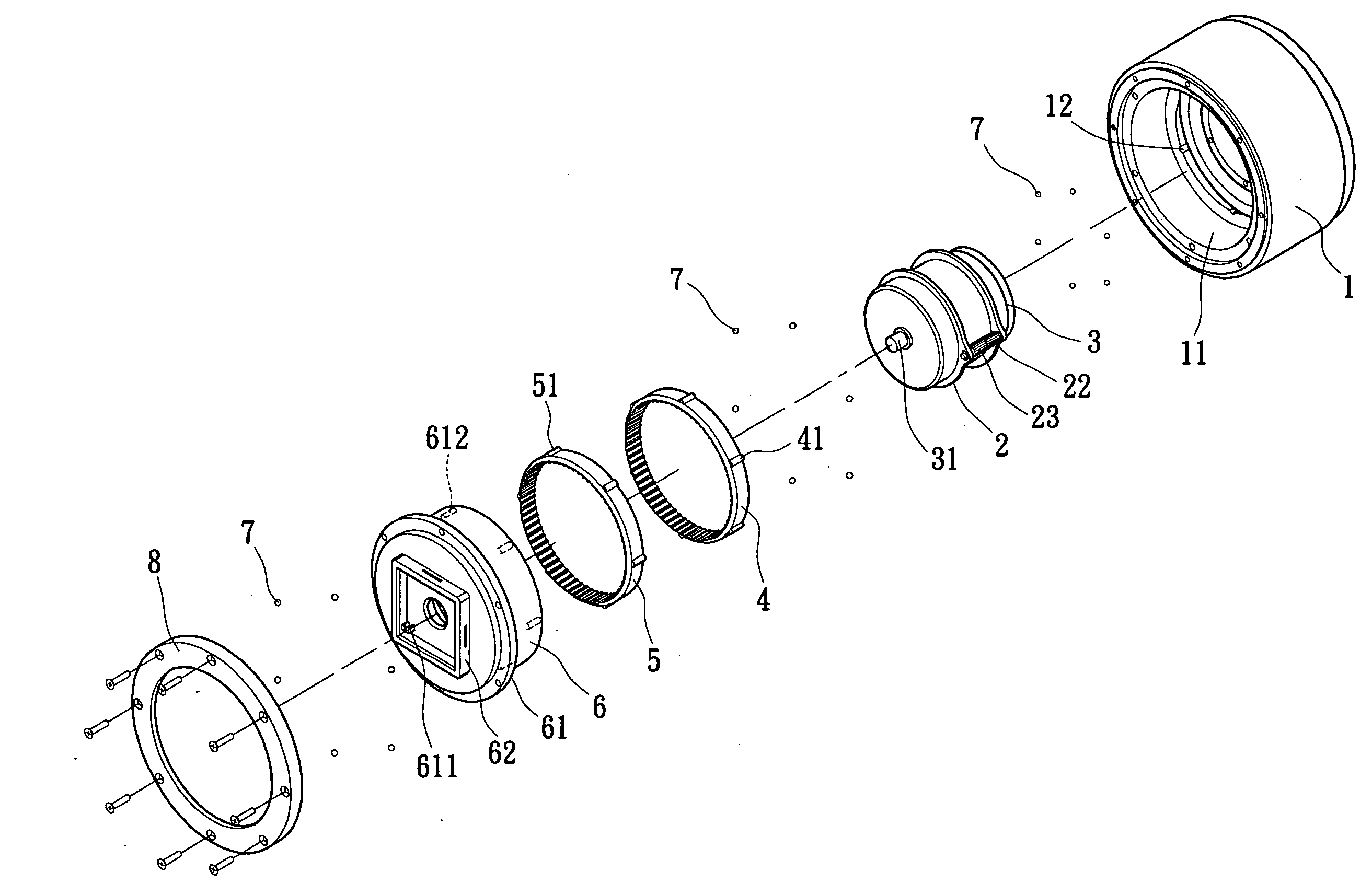
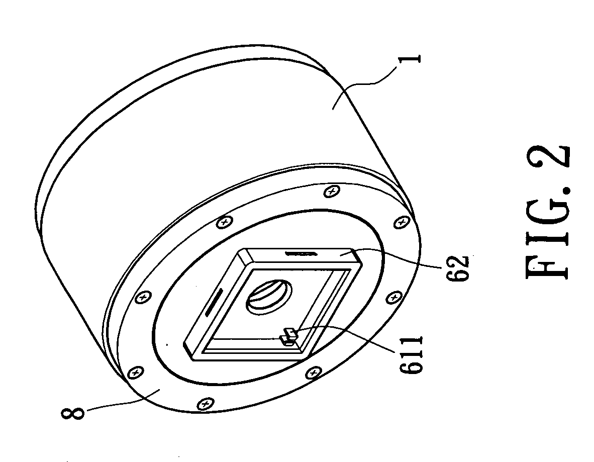
[0025]As shown in FIG. 2 and FIG. 3, a modular gear train mechanism with an internal motor according to the present invention includes a hollow casing 1, a flywheel 2, a motor 3, a fixing gear 4, a rotating gear 5, a top cap 6 and a plurality of balls 7. The casing has an opening 11, and the flywheel 2, the motor 3, the fixing gear 4 and the rotating gear 5 are received in the casing 1.

[0026]As shown in FIG. 3 and FIG. 4, two gear shafts 21 are connected to the exterior of the flywheel 2. A fastening ring 211 is mounted on one end of each gear shaft 21 to fasten the gear shaft 21 on the surface of the flywheel 2, and a gear shaft base 212 is formed on the other end of each gear shaft 21 and embedded in the flywheel 2.

[0027]As shown in FIG. 3 and FIG. 4, a first planet gear 22 and a second planet gear 23, which have the same number of teeth, are mounted on each gear shaft 21 pivotally. Two first bearings 24 are respectively mounted on two corresponding ends of each gear shaft 21. The...


PUM


Abstract

A modular gear train mechanism with an internal motor includes a hollow casing with an opening, a flywheel, a motor, a fixing gear, a rotating gear and a top cap sealing the opening. The flywheel is mounted between the interior of the top cap and the interior of the casing. A first and a second planet gears are mounted on the exterior of the flywheel pivotally. The motor received in the flywheel has a rotor shaft on which the flywheel is mounted pivotally. The fixing gear is fixed in the flywheel and engages with the first planet gear. The rotating gear is connected to an inner wall of the top cap and engages with the second planet gear. When the rotor shaft turns, the rotating gear is driven to turn and drive the top cap to turn synchronously. Accordingly, the present invention has a reduced volume and is easily used.

Description

BACKGROUND OF THE INVENTION[0001]1. Field of the Invention[0002]The present invention relates to a train mechanism, especially to a train mechanism with an internal motor.[0003]2. Description of Related Art[0004]Mechanical control systems are widely used in production scheduling in factories, pull in scheduling of trains, antiskid designs for automobiles, temperature control for cold and warm air-conditioners, robots and so on. Train mechanisms are the necessary components in mechanical control systems.[0005]As shown in FIG. 1, a conventional control system generally includes a sensor 1a, a controller 2a, a train mechanism 3a and a controlled field 4a. The controlled field 4a is a mechanical system or electronic system which needs to be controlled. The sensor 1a senses each output state 41a of the controlled field 4a. Each output state 41a and corresponding control commands 5a from a control end are input into the controller 2a. The controller 2a determines the error between the out...

Claims


Application Information

Patent Timeline
Patent Type & Authority Applications(United States)
IPC IPC(8): F16H48/06
CPCB25J9/102F16H2001/2881F16H1/28
Inventor CHANG, DIN-SHAN
Owner APLOMB TECH
Why Eureka
Try Eureka