Prosthesis deployment device with translucent distal end

Inactive Publication Date: 2009-09-10
BOSTON SCI SCIMED INC
View PDF84 Cites 40 Cited by
  • Summary
  • Abstract
  • Description
  • Claims
  • Application Information

AI Technical Summary

Benefits of technology

[0023]Thus in accordance with the present invention, a prosthesis can be optically viewed both before its release to insure an accurate positioning within a body lumen, and during its release to monitor its position both with respect to the lumen, and with respect to the delivery/deployment catheter. An endoscope or other suitable optical device can provide an image that enables the user to distinguish amo

Problems solved by technology

This approach, however, provides only a monochromatic, two-dimensional image showing a profile but no depth of field.
This advantage is lost during deployment, however, and again the image offers neither distinctions in color nor depth of field.
This approach likewise lacks the capacity for distinction

Method used


Image

  • Prosthesis deployment device with translucent distal end
  • Prosthesis deployment device with translucent distal end
  • Prosthesis deployment device with translucent distal end

Examples


Embodiment Construction

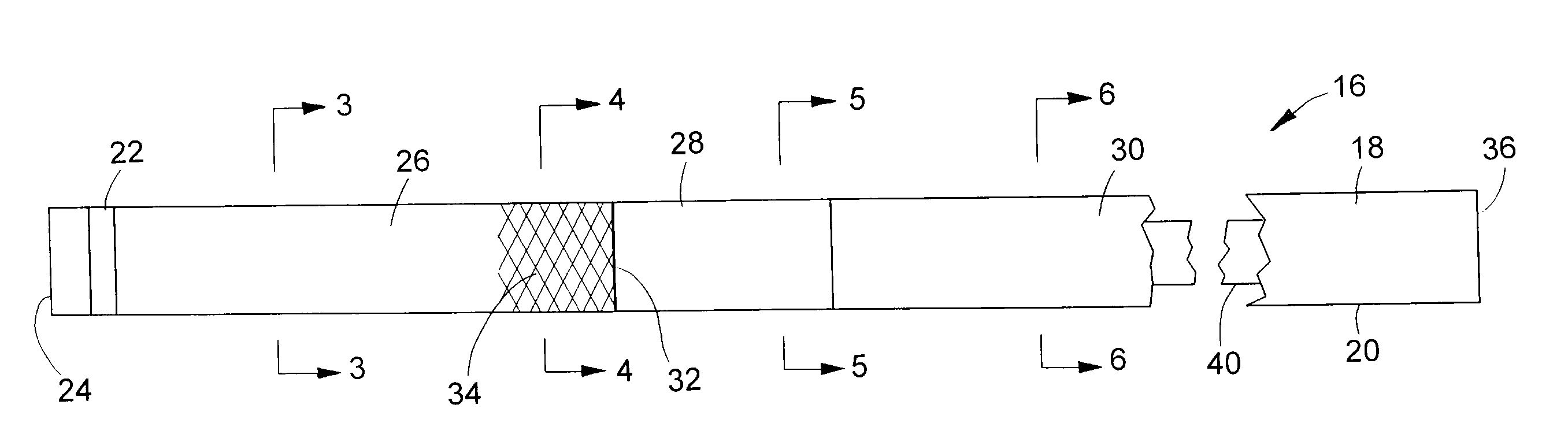
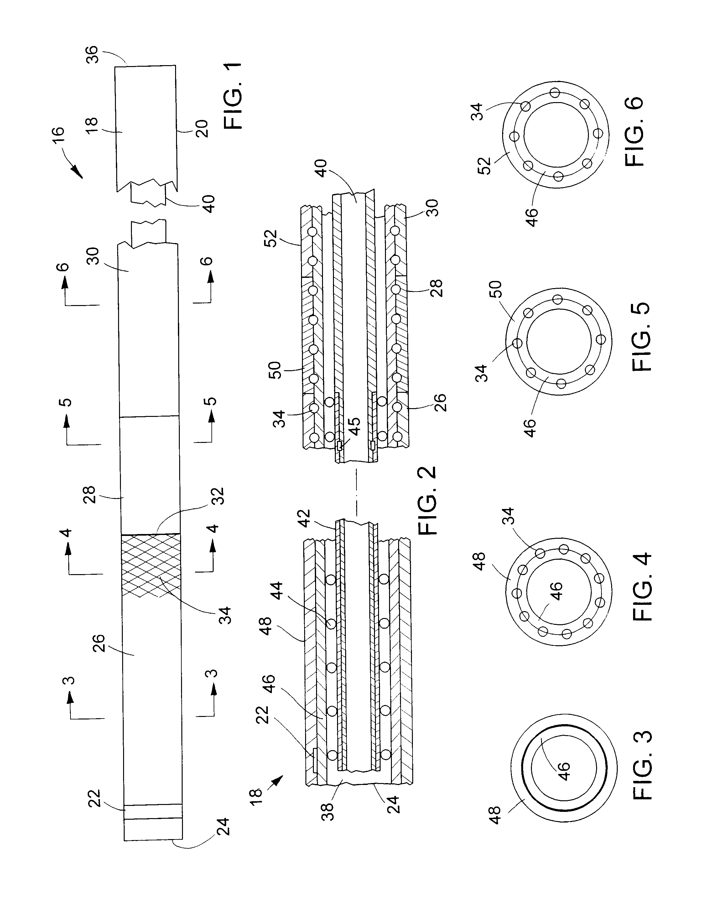
[0031]Turning now to the drawings, there is shown a device 16 for delivering a radially self-expanding prosthesis to a selected treatment site within a body cavity or body lumen, and for deploying the prosthesis, once it is positioned at the treatment site. The device includes an elongate, flexible outer catheter 18 having a tubular catheter wall 20. A radiopaque marker 22 is mounted to the catheter near its distal end 24.

[0032]Along its axial length, catheter wall 20 is divided into three sections or regions: a distal region 26; a medial region or transition region 28; and a proximal region 30. As indicated by the break, the full length of proximal region 30 is not shown in FIG. 1. The proximal region is by far the longest of the three regions. The diameter and axial length of catheter 18 can vary according to the application and size of the body lumen involved. Some typical ranges for enteral applications include a total catheter length of 135-230 cm in conjunction with a distal s...


PUM

PropertyMeasurementUnit
Polymericaaaaaaaaaa
Frictionaaaaaaaaaa
Radiopacityaaaaaaaaaa

Abstract

A prosthesis delivery and deployment device includes an elongate and flexible outer catheter. The outer catheter has a tubular wall of layered construction, including a translucent inner liner running the complete catheter length, and three outer layers including a translucent distal layer, an opaque medial layer and an opaque proximal outer layer. The outer layers are adjacent one another and are bonded to the liner. A braid composed of helically wound metal filaments is disposed between the liner and the proximal and medial outer layers, and includes a distal portion between the liner and a proximal portion of the distal outer layer. The liner and distal outer layer provide a translucent distal region of the catheter that is adapted to constrain a radially self-expanding prosthesis in a radially reduced, axially elongated state. Because the stent constraining region is translucent, an endoscope can be used to visually monitor the stent when so constrained. Radiopaque markers can be mounted to the outer catheter and to an inner catheter used to deploy the prosthesis, to afford a combined visual and fluoroscopic monitoring for enhanced accuracy in positioning the prosthesis, both before and during its deployment.

Description

CROSS-REFERENCE TO RELATED APPLICATIONS[0001]This application is a continuation of U.S. application Ser. No. 10 / 281,017, filed Oct. 25, 2002, which is a continuation of U.S. application Ser. No. 09 / 569,445, filed May 12, 2000, now U.S. Pat. No. 6,726,712 B1, which claims the benefit of priority of Provisional Application No. 60 / 134,267, filed May 14, 1999, the contents of all of which are incorporated herein by reference.BACKGROUND OF THE INVENTION[0002]The present invention relates to medical devices for delivering endoprostheses to predetermined treatment sites within body cavities or lumens, and further deploying the endoprostheses at the selected sites. More particularly, this invention relates to such devices that are capable of enabling or facilitating a tracking of the endoprostheses during deployment.[0003]A variety of patient treatment and diagnostic procedures involve the use of prostheses inserted into the body of a patient and intraluminally implanted. Percutaneous trans...

Claims


Application Information

Patent Timeline
IPC IPC(8): A61F2/06A61F2/84
CPCA61F2/95A61F2/02Y10T29/49826A61F2/966B29C66/1122B29C66/5221B29C66/712B32B27/08B32B27/322
Inventor RAEDER-DEVENS, JENNIFER E.SHELSO, SUSAN I.HEMERICK, JAMES F.SCHNEIDER, ERIC M.GETTY, HEATHER L.BORGMANN, DOREEN M.SISOMBATH, KAKAOHELGERSON, JEFFREY A.
Owner BOSTON SCI SCIMED INC
Why Eureka
Try Eureka