Eureka AIR delivers breakthrough ideas for toughest innovation challenges, trusted by R&D personnel around the world.

Device and Method for Controlling Valve

Inactive Publication Date: 2009-09-10
FUJIKOKI CORP
View PDF9 Cites 15 Cited by
  • Summary
  • Abstract
  • Description
  • Claims
  • Application Information

AI Technical Summary

Benefits of technology

[0012]Therefore, the present invention has been made in consideration of the above problems in the conventional art, and the object thereof is to provide a valve controller and the like which are convenient for users in that, even users without abundant experience and expert knowledge can obtain the optimum operation performance for a short period of time; and it can be prevented that control performance is caused to be deteriorated on the contrary in dependence on changing way of the coefficients and so on.
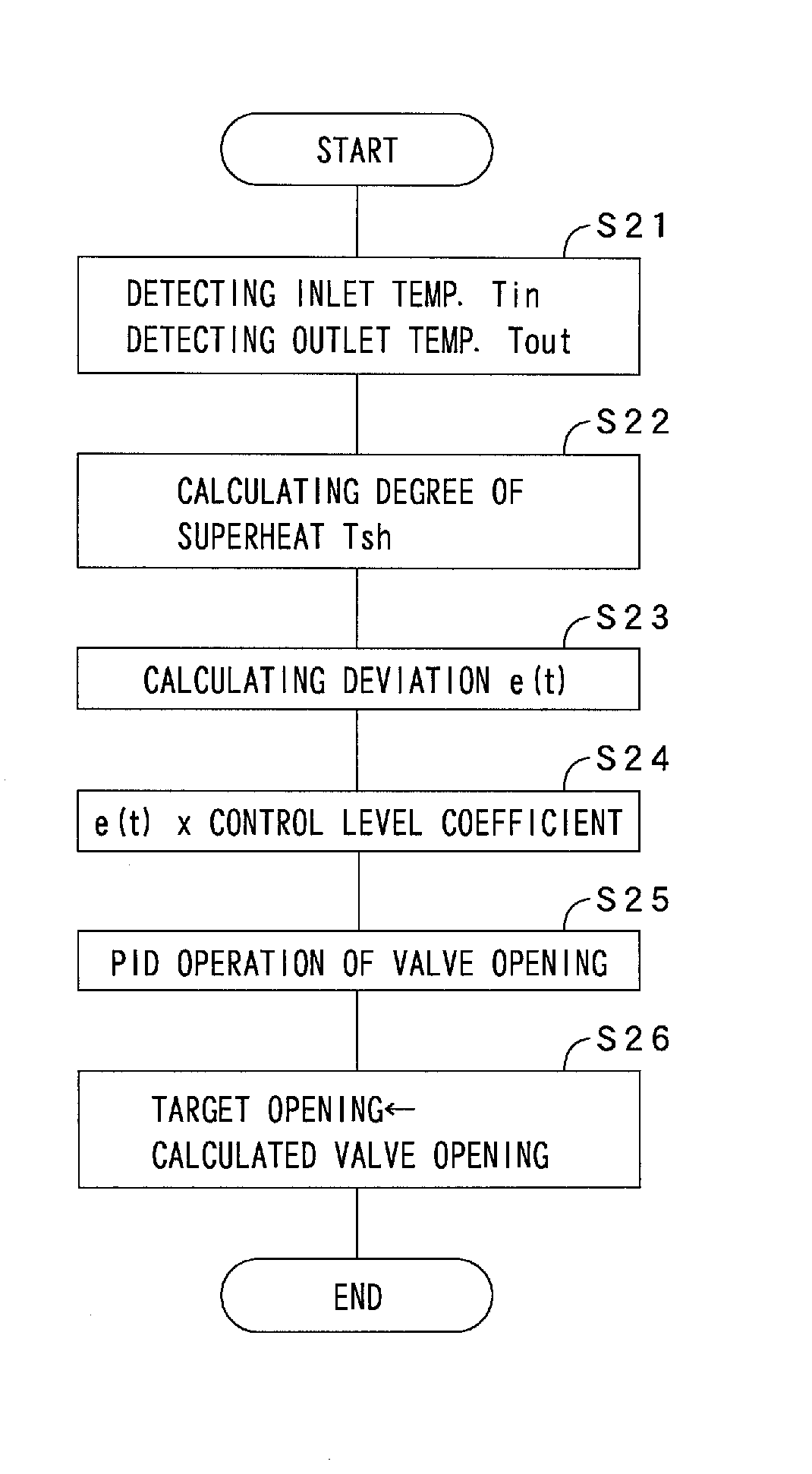
[0014]With the present invention, the control level adjusting means allows the magnitude of the valve opening calculated with the control parameter set by the automatic tuning means to be adjusted in stages, so that the work for obtaining the optimum controllability while confirming temperature responsiveness through test run with real device, real load and so on, and changing each coefficient PB, Ti and Td becomes unnecessary, so that even users without abundant experience and expert knowledge can obtain the optimum operation performance for a short period of time. In addition, it can be prevented that control performance is caused to be deteriorated on the contrary in dependence on changing way of the coefficients and so on, which provides a convenient valve controller for users.
[0015]In the above valve controller, the valve may be an expansion valve in a refrigeration cycle system, and the detected temperature may be a degree of superheat, which makes it possible to easily obtain the optimum control performance in a refrigeration cycle system with automatic tuning function for a short period of time, and so on.
[0016]In the valve controller described above, the control level adjusting means can adjust the magnitude of the valve opening calculated with the arithmetic expression by multiplying a predetermined coefficient according to the control level that can be set in stages to the deviation, the control parameter, or a changing amount of the valve opening calculated by the arithmetic expression.
[0018]Further, the present invention relates to a valve controlling method of controlling valve opening by calculating the valve opening such that a detected temperature coincides with a target temperature comprising the steps of: calculating a deviation between the detected temperature and the target temperature, calculating the valve opening by substituting at least the deviation and a set control parameter into an arithmetic expression, and automatically setting the control parameter; and adjusting a magnitude of the valve opening calculated with the automatically set control parameter in stages in accordance with a set control level. With the present invention, in the same manner as the inventions described above, it is possible to provide a convenient valve controlling method for users in that the work to obtain the optimum controllability while changing PB and other coefficients through test run with real device, real load and so on becomes unnecessary, so that even users without abundant experience and expert knowledge can obtain the optimum operation performance for a short period of time, etc.
[0019]As mentioned above, with the present invention, it is possible to provide a convenient valve controller and others for users in that even users without abundant experience and expert knowledge can obtain the optimum operation performance for a short period of time, and it can be prevented that control performance is caused to be deteriorated on the contrary in dependence on changing way of the coefficients and so on.

Problems solved by technology

However, since judging increase and decrease of each coefficient to what extent while confirming the responsiveness requires abundant experience and expert knowledge on the PID control, when less-experienced users or users with limited knowledge set the control parameters with the automatic tuning function, change of the PB, Ti and Td each in fine adjustment stage becomes inappropriate, so that it takes long time to find out the optimum coefficients, and further in dependence on changing way of the coefficients, on the contrary, there is a fear that control performance deteriorates.

Method used


Image

  • Device and Method for Controlling Valve
  • Device and Method for Controlling Valve
  • Device and Method for Controlling Valve

Examples


Embodiment Construction

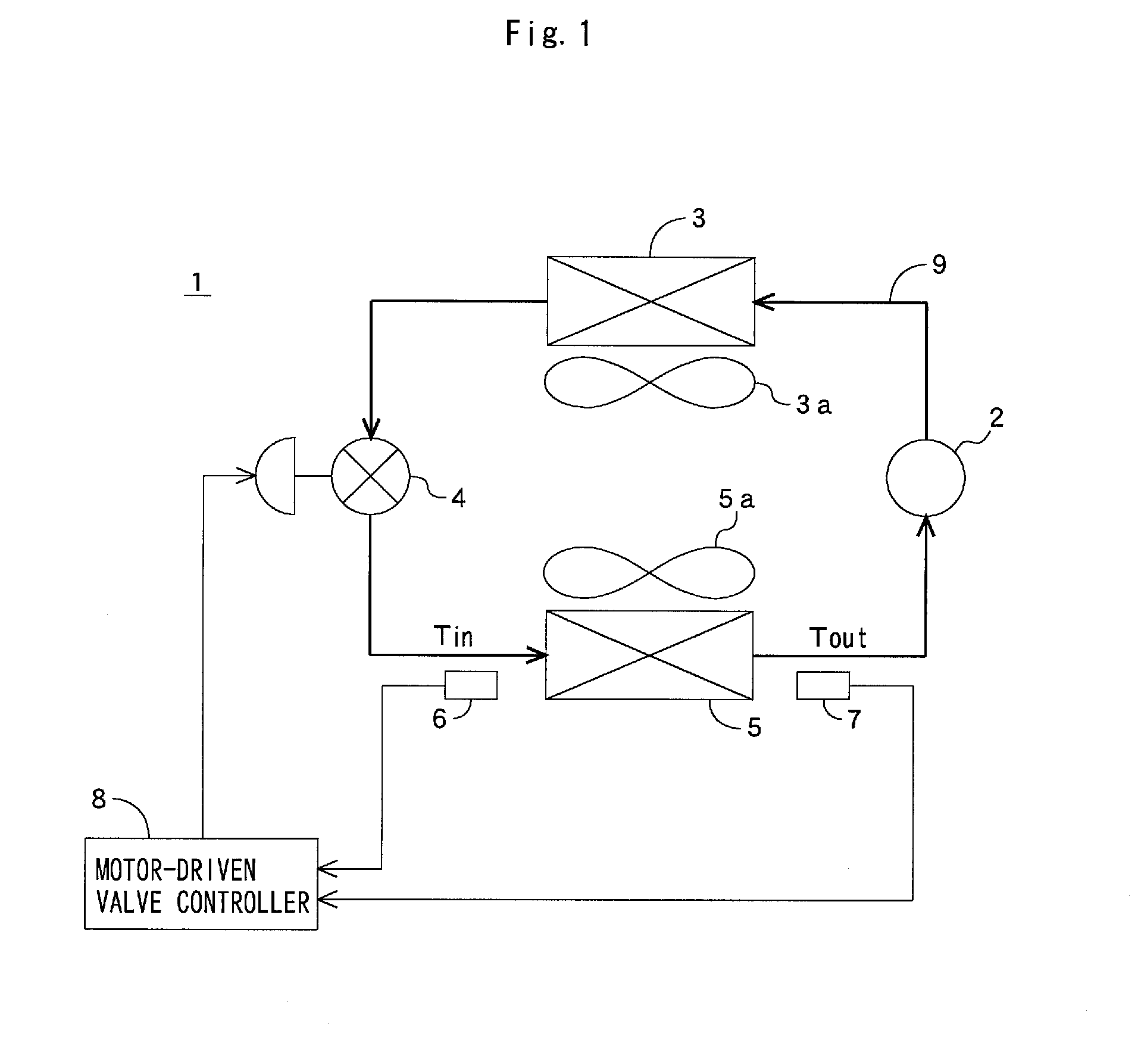
[0027]Next, embodiments of the present invention will be explained in detail with reference to drawings. In the following explanations, a valve controller of the present invention is exemplarily used for a device for controlling an expansion valve (motor-driven valve) disposed in a refrigeration cycle system.

[0028]FIG. 1 shows a refrigeration cycle system (hereinafter referred to as “system”) with a valve controller according to the present invention, and the system 1 is provided with a compressor 2, a condenser 3, a fan 3a for the condenser 3, an expansion valve (motor-driven valve) 4, an evaporator 5, a fan 5a for the evaporator 5, an inlet temperature sensor 6, an outlet temperature sensor 7 and a valve controller 8.

[0029]The compressor 2, the condenser 3, the expansion valve 4 and the evaporator 5 are connected with each other through a conduit 9, and among them circulates refrigerant. Here, the quantity of the refrigerant flowing through the conduit 9 is controlled by adjusting...


PUM


Abstract

To provide a valve controller which is convenient for users in that, even users without abundant experience and expert knowledge can obtain the optimum operation performance for a short period of time; and it can be prevented that control performance is caused to be deteriorated on the contrary in dependence on changing way of each coefficient. A valve controller 8 for controlling valve opening of an expansion valve 4 by calculating the valve opening such that a detected temperature (degree of superheat) Tsh coincides with a target temperature (degree of superheat) TS comprises: automatic tuning means for calculating a deviation e(t) between the detected temperature and the target temperature and for calculating changing amount of the valve opening m(t) by substituting at least the deviation and a set control parameter (PB, Ti, Td) into an arithmetic expression to automatically set the control parameter; and control level adjusting means for adjusting a magnitude of the valve opening calculated with the control parameter set by the automatic tuning means in stages in accordance with a set control level, and so on.

Description

CROSS-REFERENCE TO RELATED APPLICATIONS[0001]The present application claims priority to Japanese Patent Application No. 2007-324164 filed on Dec. 17, 2007.STATEMENT RE: FEDERALLY SPONSORED RESEARCH / DEVELOPMENT[0002]Not ApplicableBACKGROUND OF THE INVENTION[0003]1. Technical Field of the Invention[0004]The present invention relates to a valve controller and a valve controlling method, and more particularly to a device and the like for controlling valve opening of a motor-driven valve for adjusting the quantity of refrigerant and others.[0005]2. Description of the Related Art[0006]Motor-driven valves are adaptable for various kinds of usage such as expansion valves for controlling the quantity of refrigerant in refrigeration cycles. PID control used for controlling valve opening of the motor-driven valve also is, as disclosed in Patent document 1, a controlling method for obtaining an operation amount (opening of motor-driven valve) through calculation by substituting control paramete...

Claims


Application Information

Patent Timeline
IPC IPC(8): G05D23/19G05D7/06
CPCF25B41/062F25B2600/21F25B2600/2513G05D23/19F25B2700/21175G05B11/42G05B13/024F25B2700/21174Y10T137/1044F25B41/35Y02B30/70
Inventor OGAWA, YOSHIO
Owner FUJIKOKI CORP
Why Eureka
Eureka Blog
Learn More