
System and method for simulating motion of a multibody system

Inactive Publication Date: 2009-09-10
VRIJE UNIV BRUSSEL
View PDF0 Cites 12 Cited by
  • Summary
  • Abstract
  • Description
  • Claims
  • Application Information

AI Technical Summary

Benefits of technology

[0035]It is also an advantage of the present invention that it allows to obtain the equations of motion with a good evolution of the constraints violation errors, i.e. with less constraints violation errors than in prior art techniques.

Problems solved by technology

Nevertheless, the Hamiltonian formulation is not often used in the description of multibody dynamics.
The reason probably is that the construction of Hamilton's equations is computationally intensive and cannot compete with the recursive acceleration based algorithms, even with the advantageous behaviour during the numerical integration.
The problem of describing the dynamics of a constraint multibody system, as is e.g. the case with closed-loop systems, is even more labour-intensive and tedious.
Applying the above described methods of the prior art on closed-loop systems typically results in inefficient methods.
If e.g. the calculations are based on the use of the Jacobian of the constraint equations, which is a legal way of tackling the problem, huge obstacles are introduced when a recursive algorithm is desired, as a strong interconnection between the co-ordinates is created.
An incorrect partitioning will lead to singularity or at least bad conditioning of Φqd.
The latter inhibits the possibility to obtain recursively formulated equations of motion.
The latter solution therefore does not allow to efficiently determine the motion of a constrained mechanical system comprising multiple bodies.
In other words, the standard techniques can be used for simulating the motion of these constrained multibody systems, but the strong interdependency of the co-ordinates and their velocities makes it difficult to tailor a O(n) recursive algorithm.

Method used


Image

  • System and method for simulating motion of a multibody system
  • System and method for simulating motion of a multibody system
  • System and method for simulating motion of a multibody system

Examples


example 1

[0077]The first example 160 is a planar chain with N links 162, in the example shown in FIG. 3a there are nine links 162; one end is fixed to the non-moving environment by means of a pin-joint 164, and the other end is attached so as to be able to slide along a fixed rod 166. There are N+2 joint co-ordinates: one for each pin-joint 164 and an additional 2 for the ends of the chain. The number of degrees of freedom (DOF) is N−1, which means that 3 co-ordinates are to be chosen as dependent. The method described above will now be applied to obtain a set of Hamiltonian equations of motion. One can choose the co-ordinates related to the last body and the constraint as dependent co-ordinates: qN and qc, the last vector being a vector with 2 co-ordinates. The motion of a rigid body K can be described by the so-called spatial velocity ΩK.

ΩK=(vω)K[26]

It is possible to express the spatial velocity of a dependent body as a function of the spatial velocity of the adjacent inboard body, as will...

example 2

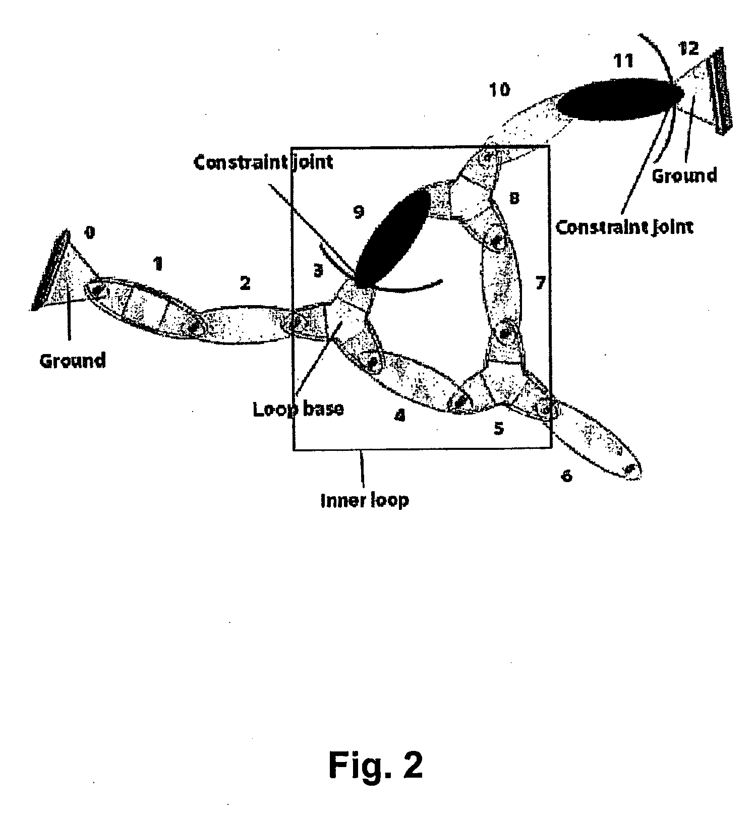
[0086]Consider the next example. It is a planar chain with a loop. This system has N−2 degrees of freedom, closing the loop introduces 2 additional constraints and one extra joint, which will be described by joint velocity (vector) {dot over (q)}C. As a consequence, there are 3 dependent co-ordinates. Body C and body L are basically the same, but a different local reference frame is used. The procedure for obtaining the dependent spatial velocities is similar to that used in previous example. Body C has spatial velocity:

ΩC=CTNVΩN+EC{dot over (q)}C=CTLVΩL  [59]

[0087]The relationship between ΩC and ΩL is described by the velocity field in the rigid body. After projection on subspace EC, one gets:

q.C=-(ECTEC)-1ECTTNVC(ΩN-TLVNΩL)[60]=CqCTTNVC(ΩN-TLVNΩL)[61]

Substitution in equation [59] results in

CCCTNV(ΩN−NTLVΩL)=0  [62]

with

CC=I+ECCqCT  [63]

This procedure can be repeated recursively for all dependent bodies. The next body N gives (premultiplying by ENTNTCF this time)

q.N=-(ENTTN+1FNCCTNV...

example 3

[0109]In the third example, the method of the present embodiment is illustrated for a planar chain with both ends fixed as described in FIG. 5a. The last two bodies, i.e. body 3 and body 4, are considered as dependent, illustrating that the method as described in the present embodiment also covers the occurrence of dependent coordinates at the end of an underlying open-loop structure, as described in the first embodiment.

Writing the principle of virtual power for the whole system yields

∑i=14[Ωi*T(P.i+Ω×Pi-Ti)]=0[237]

The major difference with an open-loop case is that the virtual joint velocities {dot over (q)}*i are not independent to each other. It is to be observed that the spatial velocities of the last two dependent bodies are known if the spatial velocity of body 2 is given. The details of the motion of body 1 does indeed not matter and it will be shown that the spatial velocities Ω3 and Ω4 can be expressed as functions of spatial velocity Ω2.

This will enable to write the princ...


PUM


Abstract

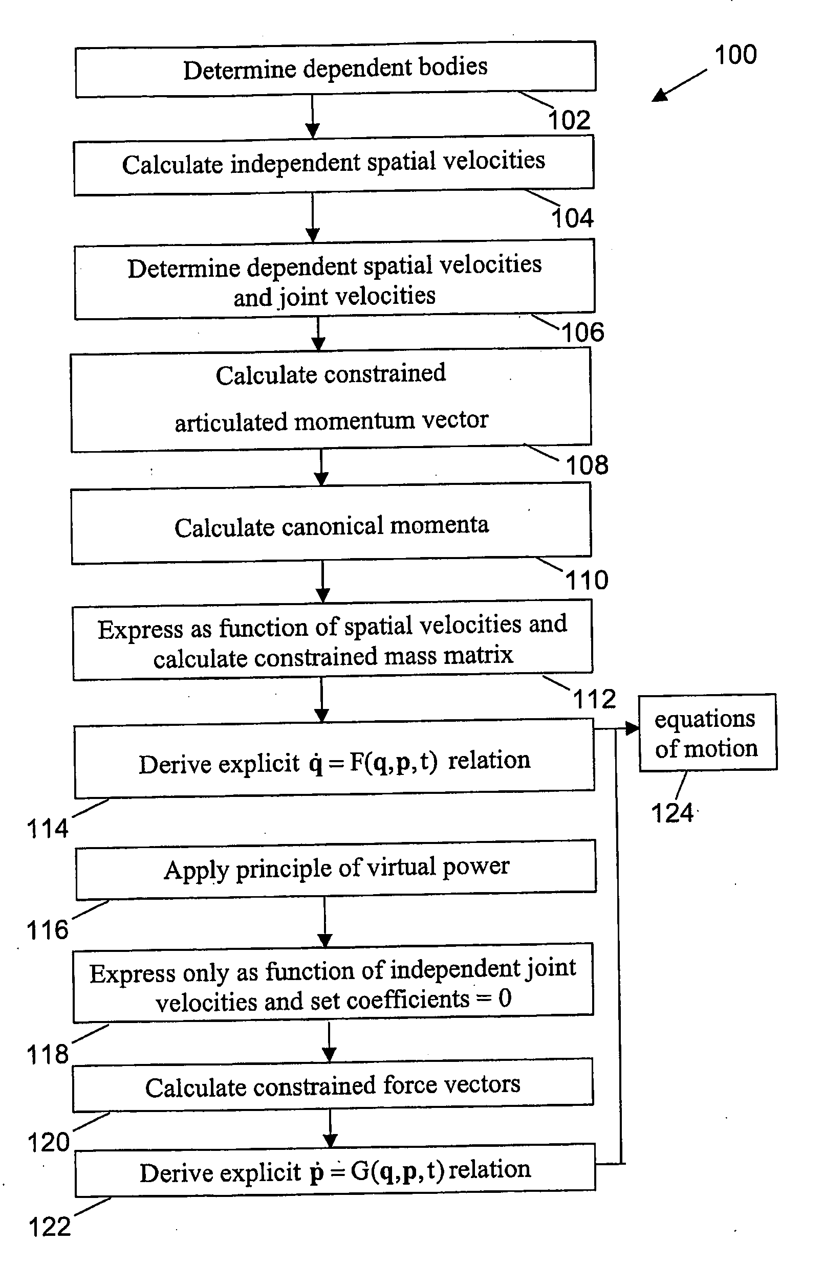
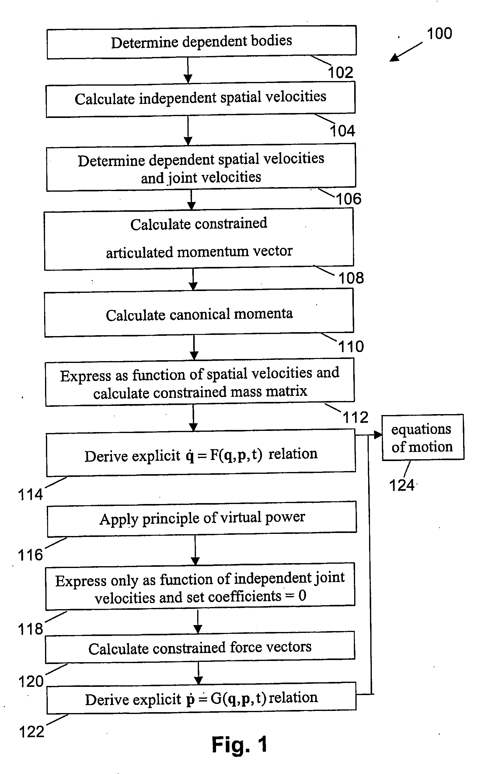
The present invention relates to a method and system for describing the motion of a closed-loop multibody mechanism. In this case, equations of motion need to be obtained for constrained multibody systems. The invention is based on a forward dynamics formulation resulting in a recursive Hamiltonian formulation for closed-loop systems using generalised co-ordinates and conjugated canonical momenta. The method allows to limit the number of arithmetical operations necessary to obtain the equations of motion with a good evolution of the constraints violation errors. Calculations can be performed based on constrained articulated momentum vectors.

Description

TECHNICAL FIELD OF THE INVENTION[0001]The present invention relates to systems and methods for visualising, simulating or predicting motion of mechanical systems comprising multiple bodies. More specifically, the present invention relates to systems and methods for efficiently describing motion of a constrained mechanical system comprising multiple bodies and systems and methods for studying, visualising, simulating or predicting the forward dynamics of a constrained mechanical system comprising multiple bodies. The methods may be used for design purposes or for verifying design performance. Further the present invention relates to controllers for control of multibody systems that use methods for simulating or predicting motion, e.g. a controller for controlling the movement of a robot or a flight or transport vehicle simulator. The control may be made at a distance, e.g. for the control of robotic vehicles for planetary exploration controlled from earth, i.e. with an unacceptable t...

Claims


Application Information

Patent Timeline
IPC IPC(8): G06F17/11G06F17/50G06G7/48
CPCG06F2217/06G06F17/5009G06F30/20G06F2111/04
Inventor NAUDET, JORISLEFEBER, DIRK
Owner VRIJE UNIV BRUSSEL
Learn More