Optical fibre with reduced polarization mode dispersion and method for obtaining an optical fibre with reduced polarization mode dispersion

a technology of optical fibers and polarization modes, applied in the field of optical fibres, can solve the problems of affecting the polarization state of optical fibres, and breaking the circular symmetry, and achieve the effect of reducing the pmd coefficient of optical fibres

Inactive Publication Date: 2005-07-19
PIRELLI CAVI E SISTEMI SPA +1
View PDF10 Cites 7 Cited by
  • Summary
  • Abstract
  • Description
  • Claims
  • Application Information

AI Technical Summary

Benefits of technology

[0022]The inventors have also found that a substantially periodic evolution of the DGD along a short section of an optical fiber is advantageous, as it allows to significantly reduce the PMD coefficient of an optical fibre of arbitrary length, down to values of 0.05 ps / km1 / 2 or lower. Advantageously, the obtained PMD coefficient can be lower than 0.02 ps / km1 / 2.

Problems solved by technology

In practical single mode fibres, however, various imperfections such as asymmetrical lateral stress and / or a non-circular core typically break the circular symmetry of the ideal modes.
However, in ordinary, non polarization-preserving fibres the birefringence causing mechanisms act on the fibre in a substantially unpredictable manner.
Thus, the polarization state of the guided light will typically evolve through a random sequence of states along the fibre, with the polarization state at the fiber output typically being both unpredictable and unstable.
Eventually, however, the state of polarization evolves away from the initial linear state as a result of power leaking over to the other polarization mode.
This leakage of power (mode coupling) occurs because of variations in the birefringence along the fiber, caused by the random perturbations.
PMD in conventional single mode fibres results in harmful signal distortion and is undesirable, especially for applications that involve high bit rates (e.g. equal to or greater than 10 Gbit / s) or analog transmission (e.g. for optical fibre analog CATV systems).
Unfortunately, very high spin rates are generally required to deal with the asymmetries of typical fibres, e.g. spin rates greater than 5000 rpm.
Spinning a preform at such rates is not a practical solution for commercial fibre production.
This result is not completely satisfactory.

Method used


Image

  • Optical fibre with reduced polarization mode dispersion and method for obtaining an optical fibre with reduced polarization mode dispersion
  • Optical fibre with reduced polarization mode dispersion and method for obtaining an optical fibre with reduced polarization mode dispersion
  • Optical fibre with reduced polarization mode dispersion and method for obtaining an optical fibre with reduced polarization mode dispersion

Examples


examples

[0153]1) As a first example, a sinusoidal spin rate function has been considered. This function has only odd harmonics. In the above introduced adimensional system, such spin rate function may be written as

γ(s)=2γ1 cos(εs)

and the corresponding integral function G(s) reads as G⁡(s)=∫0s⁢2⁢γ1⁢cos⁡(ξ⁢ ⁢s′)⁢ⅆs′=2⁢γ1ξ⁢sin⁡(ξ⁢ ⁢s)

[0154]Under the short period assumption, the DGD is periodic if the following condition is satisfied (see (13)): ∫0χ / 2⁢cos⁡(2⁢γ1ξ⁢sin⁡(ξ⁢ ⁢s))⁢ⅆs=2⁢πξ⁢J0⁡(2⁢γ1ξ)=0

where J0 is the first kind Bessel function of order 0.

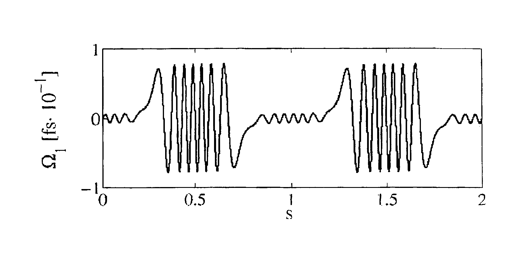
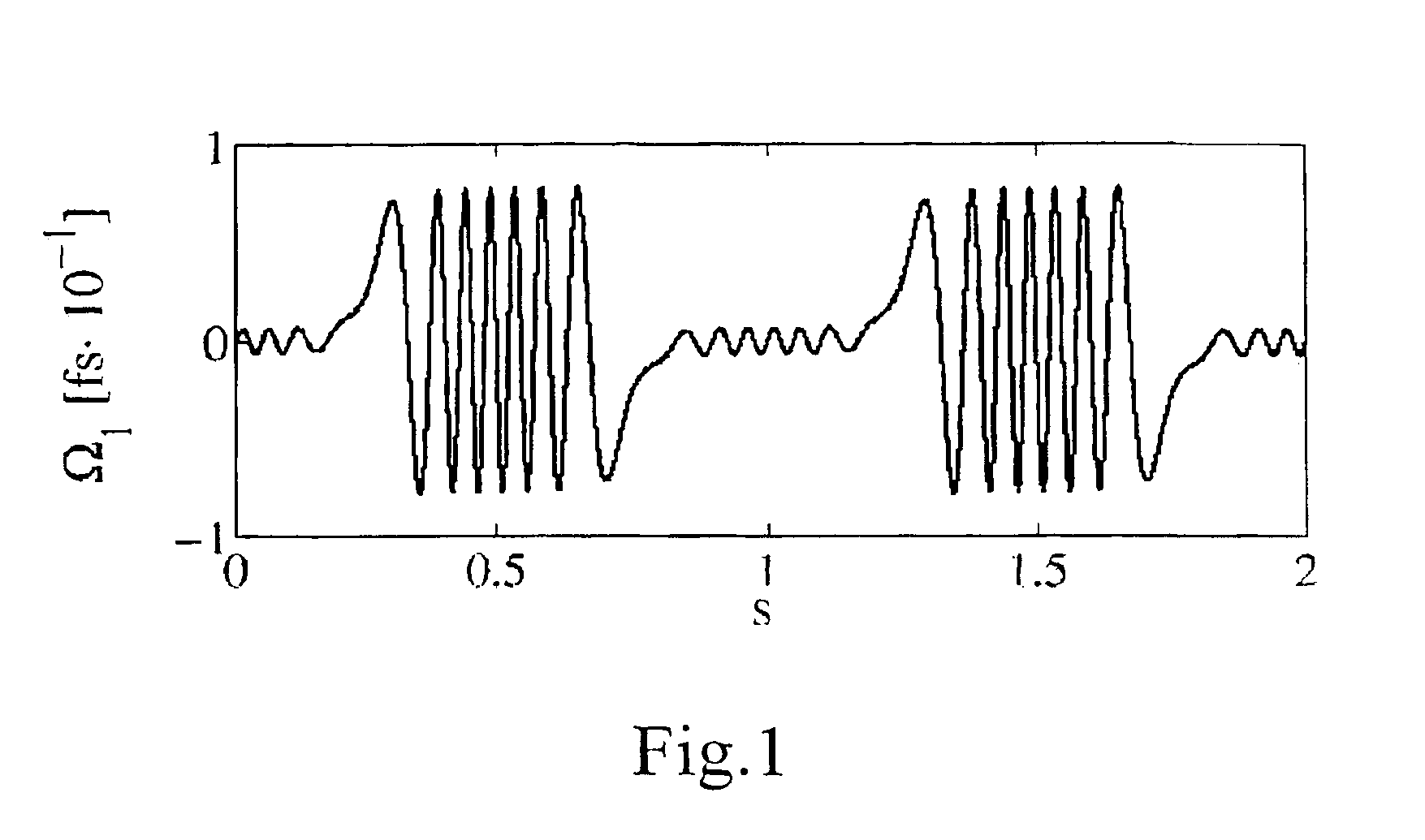
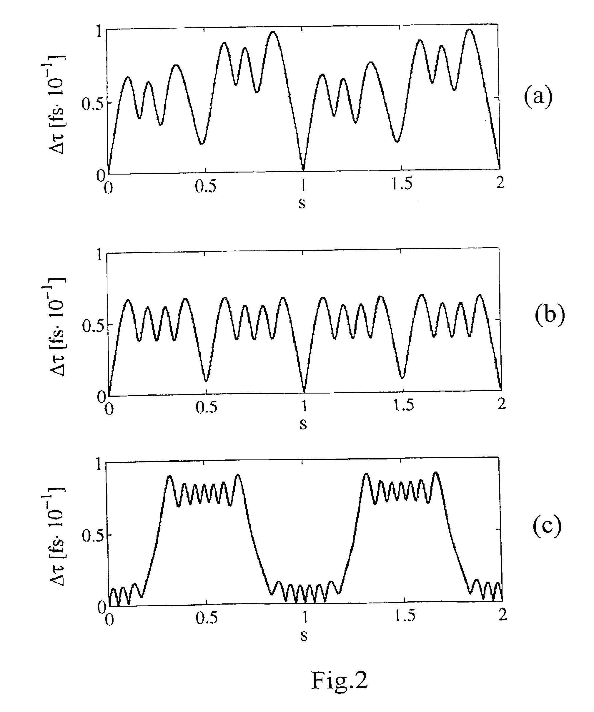
[0155]Exemplarily, by setting ξ=2π, a possible value γ1 which can be found in order to satisfy the above condition is 37.05. By setting these parameters in the spin function and numerically solving equation (6), the periodic evolution of the PDV and of the DGD was verified, as it is shown, respectively, in FIG. 1 and FIG. 2(c). As analitically predicted, Ω1 has zero mean and, hence, Δτ is a periodic function of distance with the same period as Ω1. For...


PUM

PropertyMeasurementUnit
speedaaaaaaaaaa
beat length LBaaaaaaaaaa
lengthaaaaaaaaaa

Abstract

A method for determining at least one parameter of a periodic spin function α(z) with period p, to be applied to an optical fiber along its length z during a drawing process. At least one parameter is selected so that (I) where ε1 is about 0.05 and y1 is the first of the three components y1(z), y2(z), y3(z) of a periodic function y(z) of period p such that (II) where LB is an expected beat length of said optical fiber and α(z) is the derivative of the spin function α(z) with respect to the length z. The method is effective for substantially reducing the PMD of optical fibers drawn when applying a spin function.

Description

CROSS REFERENCE TO RELATED APPLICATIONS[0001]This application is a national phase application based on PCT / EP01 / 07241, filed Jun. 27, 2001, the content of which is incorporated herein by reference, and claims the priority of European Patent Application No. 00114559.8, filed Jul. 6, 2000, the content of which is incorporated herein by reference, and claims the benefit of U.S. Provisional Application No. 60 / 218,057, filed Jul. 13, 2000, the content of which is incorporated herein by reference.BACKGROUND OF THE INVENTION[0002]1. Field of the Invention[0003]This invention relates to optical fibres, in particular to single mode optical fibres with reduced polarization mode dispersion (PMD). This invention also relates to a method for obtaining an optical fibre with reduced PMD.[0004]The invention may apply to all kinds of optical fibres, as for example dispersion-unshifted fibres, dispersion-shifted fibres, non-zero-dispersion fibres, dispersion-compensating fibres, fibres for optical am...

Claims


Application Information

Patent Timeline
Patent Type & Authority Patents(United States)
IPC IPC(8): C03B37/03C03B37/02C03B37/027G02B6/10
CPCC03B37/027C03B37/02745C03B37/032G02B6/02285G02B6/105C03B2203/36C03B2205/06C03B2203/19
Inventor GALTAROSSA, ANDREAPIZZINAT, ANNAPALMIERI, LUCA
Owner PIRELLI CAVI E SISTEMI SPA
Why Eureka
Try Eureka