Compact configuration for cryogenic pumps and turbines

a cryogenic pump and turbine technology, applied in the field of cryogenic machines, can solve the problems of high cost of stainless steel vessels, explosion and flammability, heavy and more expensive vessels with large diameters

Inactive Publication Date: 2009-09-17
ELLIOTT CO
View PDF6 Cites 16 Cited by
  • Summary
  • Abstract
  • Description
  • Claims
  • Application Information

AI Technical Summary

Benefits of technology

[0010]An aspect of this invention is to provide a co

Problems solved by technology

LNG is a fuel, hence it is explosive and flammable.
To avoid explosion and fire hazards the aluminum cryogenic pumps, expanders and turbines are mounted in a stainless steel vessel since stainless steel is not flammable like aluminum, however stainless steel cryogenic vessels must be certified for high pressure (due to the pump and turbine pressure) and must be manufactured of expensive stainless steel such as also used in aerospace technology.
So the stainless steel vessels are very expensive.
Since the thickness

Method used


Image

  • Compact configuration for cryogenic pumps and turbines
  • Compact configuration for cryogenic pumps and turbines
  • Compact configuration for cryogenic pumps and turbines

Examples


Embodiment Construction

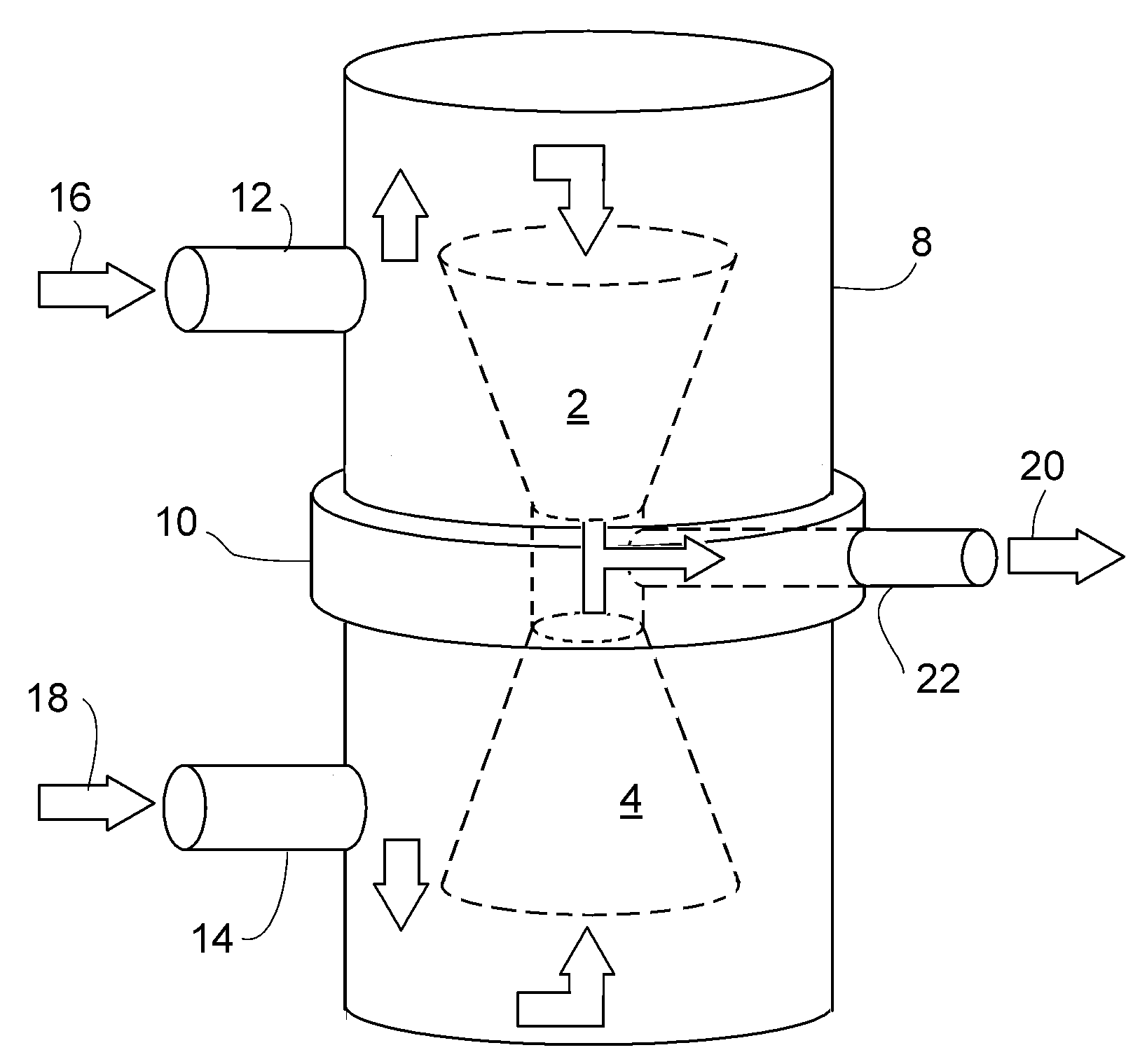
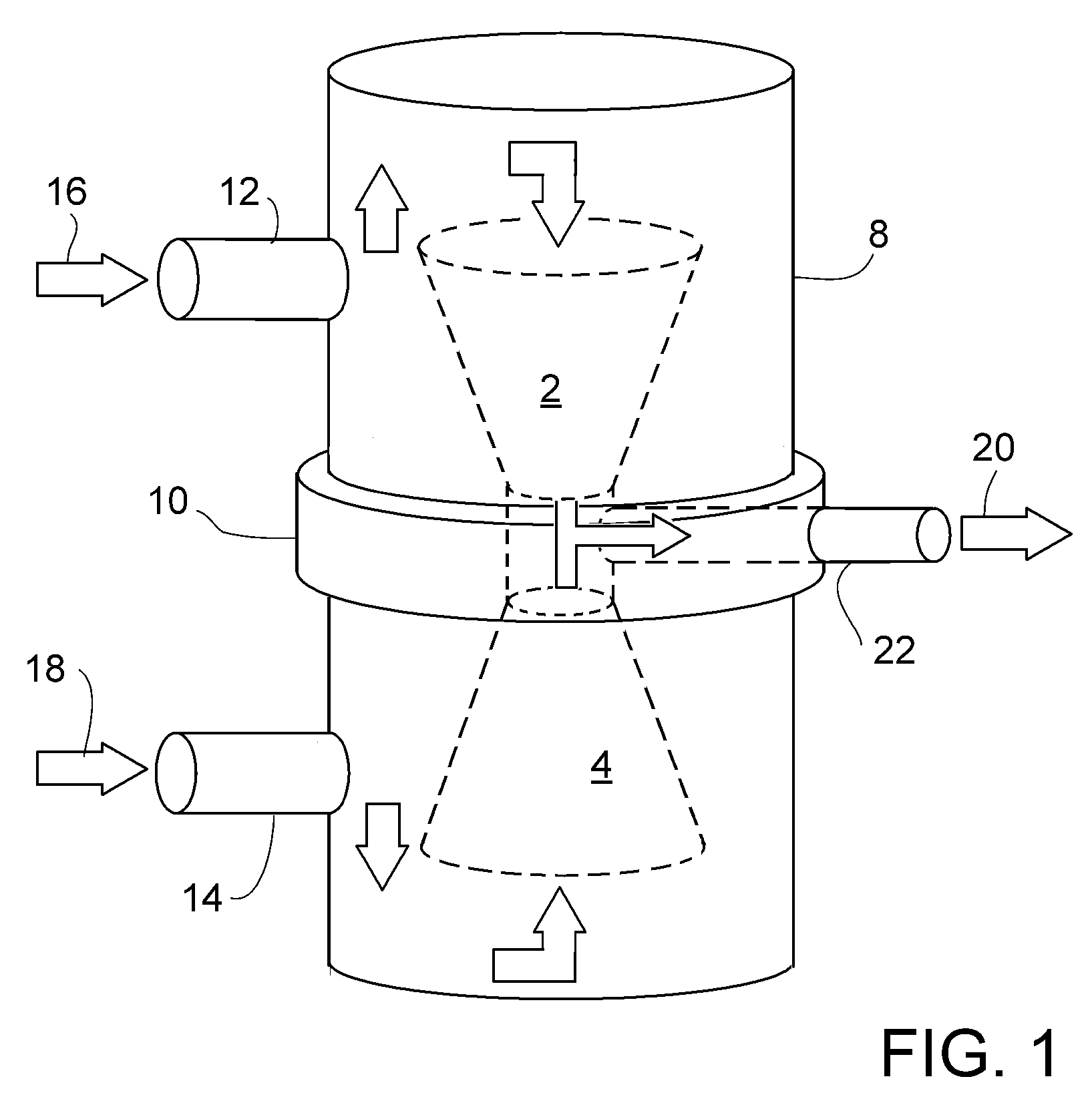
[0019]Referring to FIG. 1, two pumps, 2 and 4, are illustrated to be mounted in a common cryogenic vessel 8 by means of an intermediate support plate 10 and configured in parallel to create higher flow with less risk and lower cost than two pumps in separate vessels. The vessel 8 defines two cryogenic liquid inlets, 12 and 14, through which low pressure suction streams, 16 and 18, are drawn respectively into the pumps, 2 and 4. The outputs of the pumps are combined in a relatively high pressure discharge 20 via vessel outlet 22. The pumps can be run together or separately, but preferably operated at the same speed when in parallel operation. Significant advantages of this embodiment include partial capacity flexibility.

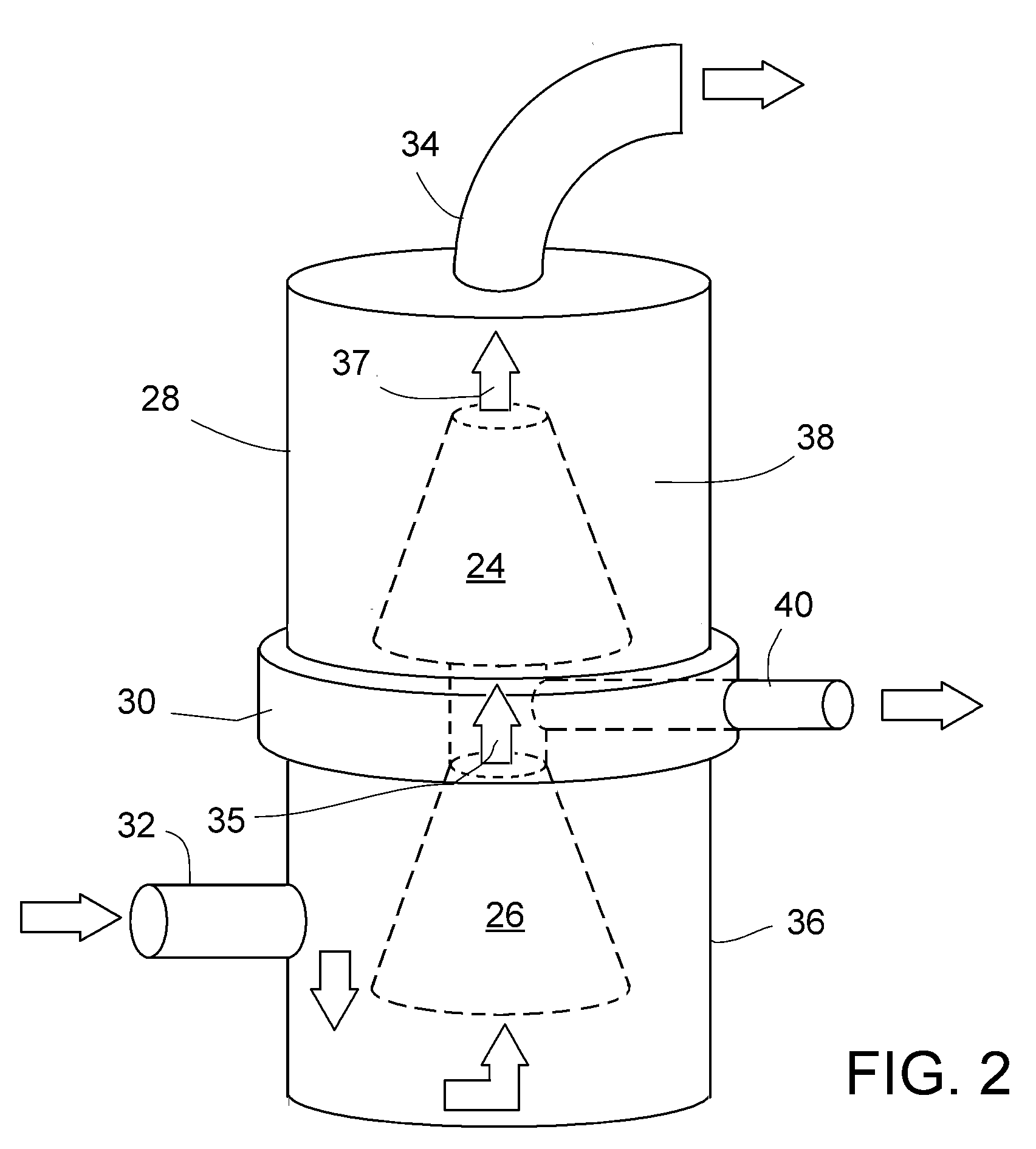
[0020]Referring to FIG. 2, two pumps, 24 and 26, are illustrated to be mounted in a common cryogenic vessel 28 by means of an intermediate support plate 30 and configured in series to create relatively higher pressure flow with less risk and lower cost than two pumps ...


PUM


Abstract

A single cryogenic liquid vessel in which two cryogenic machines are disposed, supported and operable in tandem. In one embodiment the two cryogenic machines are operable in series or individually, and in another embodiment the two cryogenic machines are operable in parallel or individually. Preferably the machines are supported intermediately relative to the vessel, or at a top of the vessel. In various embodiments the machines are pumps or turbines or expanders.

Description

[0001]This invention claims the filing date benefit of U.S. Provisional Application 60 / 705,800 filed Aug. 6, 2005 by Joel V. Madison.BACKGROUND OF THE INVENTION[0002]This invention relates in general to cryogenic machines, such as pumps and turbines designed to operate at cryogenic temperatures, and in particular to two separate cryogenic machines mounted in a common cryogenic pressure vessel and configured to operate in series, in parallel or individually.[0003]For the purposes of this application, cryogenic liquids are those that boil at temperatures at or below −100° C. under atmospheric pressures. An example is liquefied natural gas (LNG) that is typically stored at cryogenic temperatures of about −162° C. (−260° F.) and at substantially atmospheric pressure.[0004]Cryogenic pumps, expanders and turbines are manufactured of aluminum alloys suitable for low temperatures, the same alloys used in aerospace technology. These cryogenic machines are mainly used for liquefied hydrocarbo...

Claims


Application Information

Patent Timeline
IPC IPC(8): F17C9/00
CPCF17C1/00F04B37/08F25J1/0022F25J1/0035F25J1/0042F25J1/0257F25J1/0271F25J2235/60F25J2240/04F25J2240/30
Inventor MADISON, JOEL V.
Owner ELLIOTT CO
Why Eureka
Try Eureka