Power Source Apparatus for Vehicle, Vehicle and Method of Controlling Power Source Apparatus

a technology of power source apparatus and vehicle, which is applied in the direction of electric devices, gas pressure propulsion mounting, and driver interaction, etc., and can solve problems such as regenerative braking

Active Publication Date: 2009-09-17
TOYOTA JIDOSHA KK
View PDF5 Cites 39 Cited by
  • Summary
  • Abstract
  • Description
  • Claims
  • Application Information

AI Technical Summary

Benefits of technology

[0027]According to the present invention, a power source apparatus for a vehicle can be realized, which can ma

Problems solved by technology

When the operating point of the motor determined by the torque and the rotation speed is abnormal, however, it is possible that an output voltage of a step-up co

Method used


Image

  • Power Source Apparatus for Vehicle, Vehicle and Method of Controlling Power Source Apparatus
  • Power Source Apparatus for Vehicle, Vehicle and Method of Controlling Power Source Apparatus
  • Power Source Apparatus for Vehicle, Vehicle and Method of Controlling Power Source Apparatus

Examples


embodiment 1

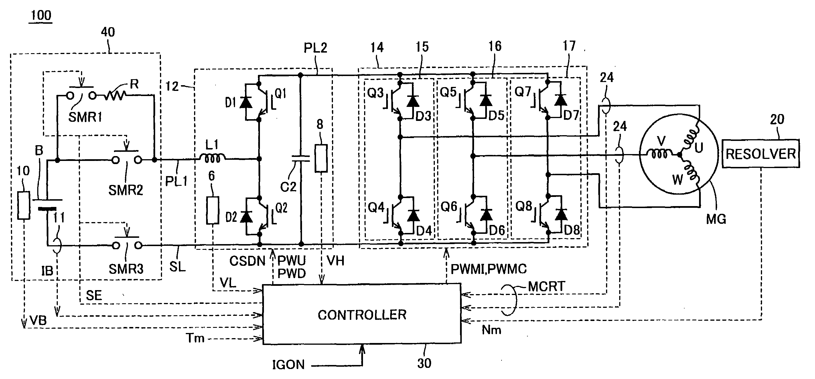
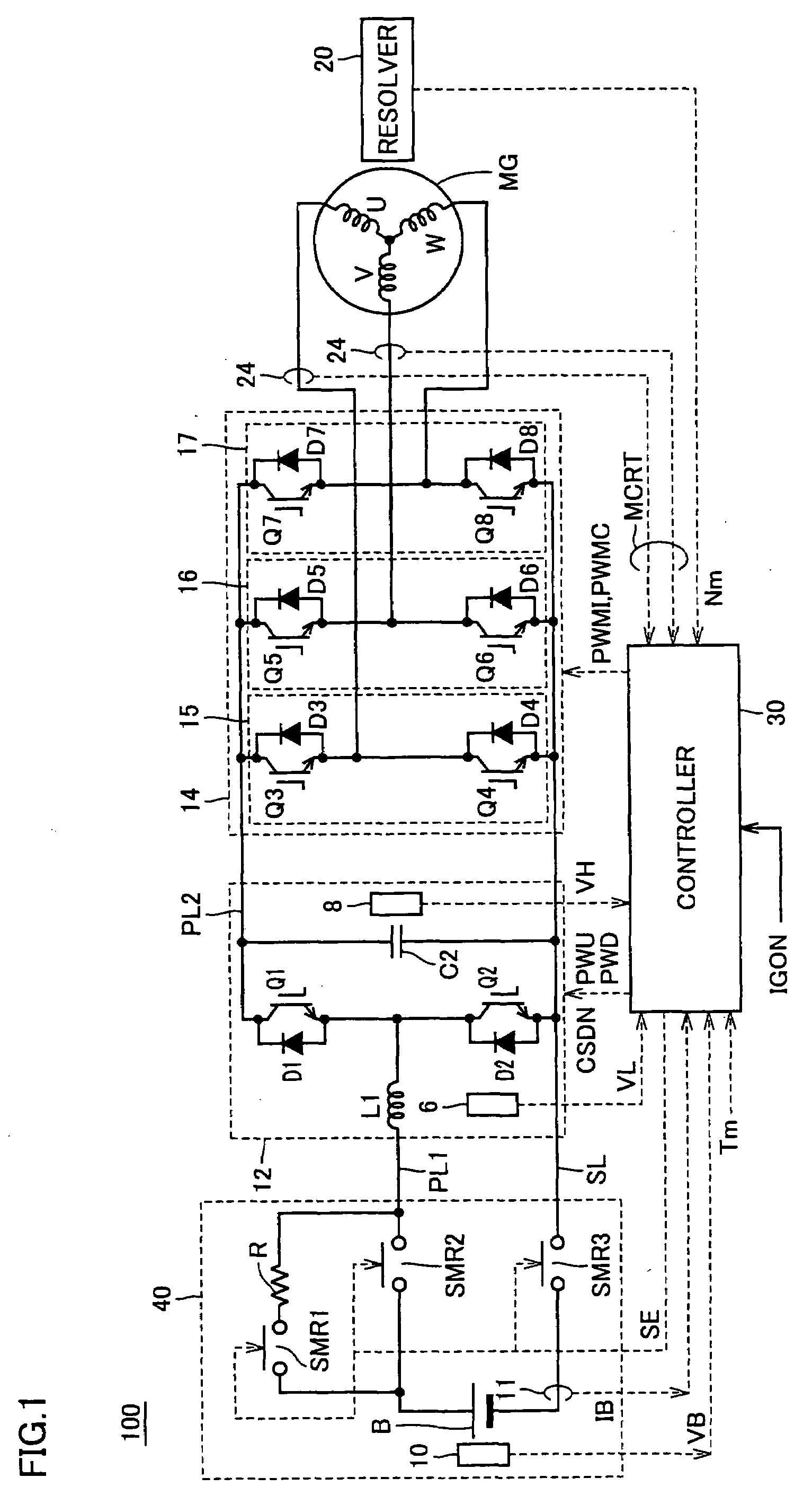
[0039]FIG. 1 is a circuit diagram showing a configuration related to motor generator control of a vehicle 100 in accordance with Embodiment 1 of the present invention.

[0040]Referring to FIG. 1, vehicle 100 includes a battery unit 40, a motor generator MG, an inverter 14 provided corresponding to motor generator MG, a step-up converter 12, a resolver 20, a current sensor 24, a controller 30 and wheels, not shown.

[0041]Battery unit 40 and step-up converter 12 are electrically connected by a power supply line PL1 and a ground ling SL.

[0042]Battery unit 40 includes a battery B, a system main relay SMR3 connected between a negative electrode of battery B and the ground line SL, a system main relay SMR2 connected between a positive electrode of battery B and the power supply line PL1, and a system main relay SMR1 and a limiting resistor R connected in series between the positive electrode of battery B and the power supply line PL1. State of conduction / non-conduction of system main relays ...

embodiment 2

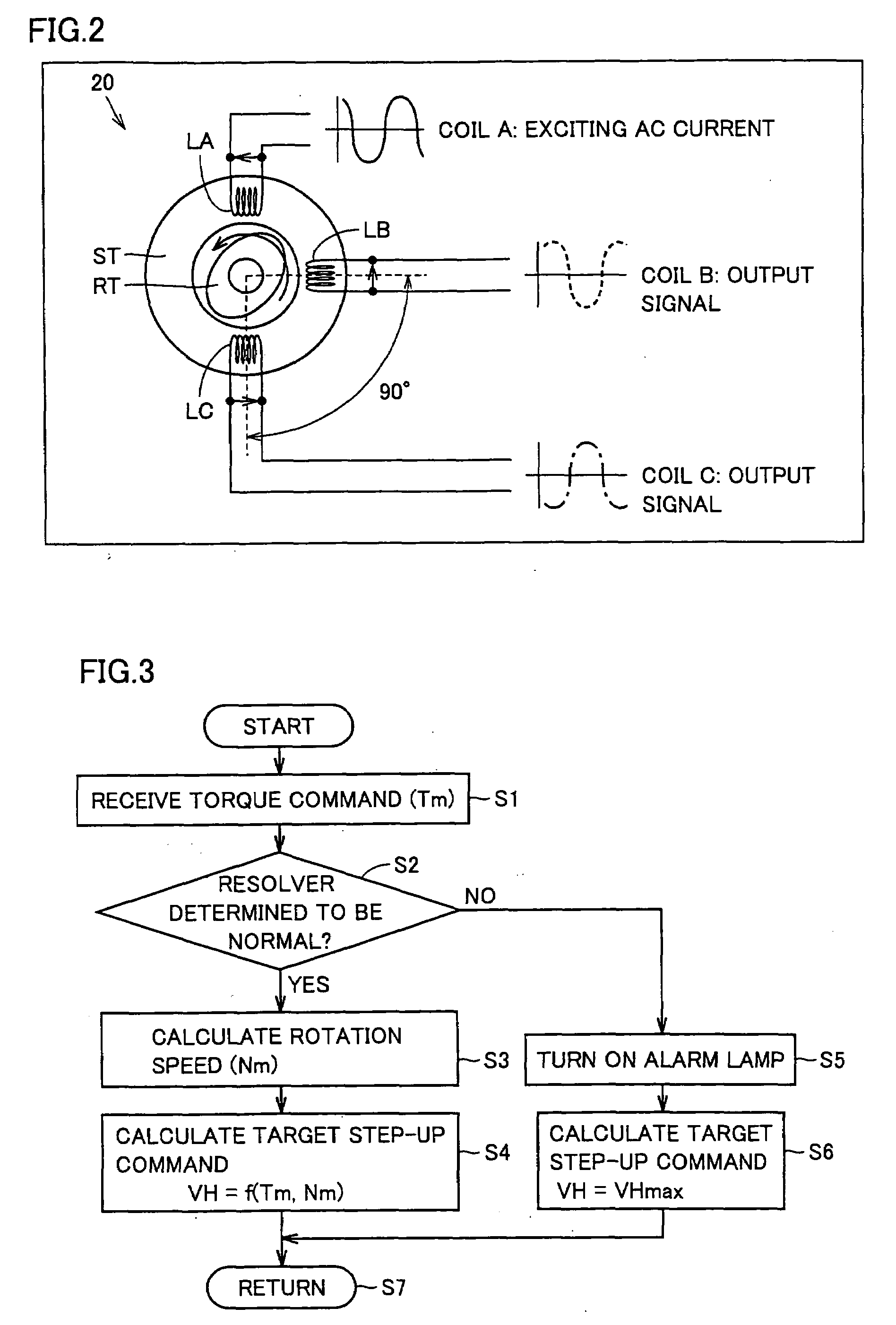
[0078]In Embodiment 1, it is described that the target step up command of the step-up converter is increased to the maximum when the rotation speed of the driving motor cannot correctly be detected. If the motor rotation speed can be correctly calculated by using a signal other than the output of the resolver that seems to be defective, the target step-up voltage VH may be calculated based thereon, using the map of FIG. 4.

[0079]FIG. 5 is a circuit diagram representing a configuration of a vehicle 200 in accordance with Embodiment 2. Vehicle 200 is a hybrid vehicle using both a driving motor and an engine.

[0080]Referring to FIG. 5, vehicle 200 has a configuration corresponding to that of vehicle 100 described with reference to FIG. 1, with motor generator MG replaced by a motor generator MG2 and controller 30 replaced by a controller 230. Vehicle 200 further includes a motor generator MG1, an inverter 22 provided corresponding to motor generator MG1, a current sensor 25 detecting a c...

embodiment 3

[0133]There is a four-wheel-drive hybrid vehicle having a motor for driving rear wheels in addition to a motor for driving front wheels. By driving the rear wheels by a motor independent from the motor for driving the front wheels, a transfer or a propeller shaft, which is essential in a general four-wheel-drive system, becomes unnecessary. This reduces driving loss, and because of the additional effect of regenerative power attained by the motor generator for the rear wheels, more fuel-efficient running than a common four-wheel-drive vehicle can be expected.

[0134]FIG. 9 is a block diagram showing a configuration of a hybrid vehicle 300 in accordance with Embodiment 3.

[0135]Referring to FIG. 9, vehicle 300 includes battery unit 40, step-up converter 12, inverters 14 and 22, motor generators MG1 and MG2, engine 4, power split device PSD, and resolvers 20 and 21. These components are the same as those of vehicle 200 in accordance with Embodiment 2 and, therefore, description thereof w...


PUM


Abstract

A vehicle (100) includes a motor generator (MG) and an inverter (14) driving the motor generator (MG). A power source apparatus for the vehicle includes a battery (B) as an electric storage device, a step-up converter (12) stepping up a voltage of the electric storage device and supplying it to the inverter, and a controller (30) indicating a target step-up voltage in accordance with a target state of operation of the motor generator (MG) to the step-up converter (12). If it is determined that a current operation state signal of the motor generator (MG) is abnormal, the controller (30) increases the target step-up voltage to a maximum value. Preferably, the vehicle (100) further includes a resolver (20) detecting rotation speed of a rotor of motor generator (MG). The controller (30) determines that the operation state signal is abnormal if an output of the resolver (20) does not satisfy a prescribed condition.

Description

TECHNICAL FIELD[0001]The present invention relates to a power source apparatus for a vehicle and to a vehicle. Particularly, the present invention relates to a power source apparatus for a vehicle in which a power supply voltage of an electric storage device is stepped up to be supplied, as well as to the vehicle.BACKGROUND ART[0002]Recently, electric vehicles, hybrid vehicles and fuel-cell vehicles have attracting attention as environmentally friendly vehicles.[0003]Such a vehicle mounts an electric storage device such as a high-voltage battery higher than 100V, to rotate motors and driving the vehicle using power from the electric storage device.[0004]A configuration for stepping up a power supply voltage of the electric storage device and supplying the stepped-up voltage to an inverter driving a motor in such a vehicle has been studied.[0005]Japanese Patent Laying-Open No. 10-066383 discloses a controller for driving a permanent magnet type synchronous motor having such a voltage...

Claims


Application Information

Patent Timeline
IPC IPC(8): H02P27/00H02P27/06B60K6/445B60K6/448B60K6/52B60L9/18B60W10/08B60W10/26B60W20/00H02M7/48H02P5/74
CPCB60L11/14Y02T10/6217B60L2250/30H02P5/74H02P27/08H02P2201/09Y02T10/7005Y02T10/7077Y02T10/7225Y10S903/904Y10S903/902B60L11/123B60L15/007Y02T10/644B60L2210/14B60L50/16B60L50/61Y02T10/62Y02T10/64Y02T10/70Y02T10/7072Y02T10/72B60L2240/421B60Y2200/91B60Y2200/92B60Y2400/3084
Inventor AMANO, MASAYA
Owner TOYOTA JIDOSHA KK
Why Eureka
Try Eureka