RFID tag using monopole antenna

a radio frequency identification and monopole technology, applied in the field of identification tags, can solve the problems of poor readable distance of the conventional rfid tag b>1/b>, rather high production cost, and substantial thickness of the entire tag, so as to achieve easy manufacturing, reduce production cost, and increase the readable distance

Inactive Publication Date: 2009-09-17
CHINA STEEL
View PDF6 Cites 6 Cited by
  • Summary
  • Abstract
  • Description
  • Claims
  • Application Information

AI Technical Summary

Benefits of technology

[0009]The RFID tag of the present invention can be disposed on a surface of an object (metal or nonmetal object) to be measured, or disposed in an inner accommodation space of the object to be measured, so the RFID tag is widely used in various applications. Additionally, the RFID tag of the present invention is easily manufactured, so the production cost can b

Problems solved by technology

The conventional RFID tag 1 is disposed on different package structures or containers, but a readable distance of the conventional RFID tag 1 is not improved.
Furthermore, the specification of U.S. Pat. No. 6,914,562 explicitly discloses that, at UHF frequencies, defined as a band in the range

Method used


Image

  • RFID tag using monopole antenna
  • RFID tag using monopole antenna
  • RFID tag using monopole antenna

Examples


Embodiment Construction

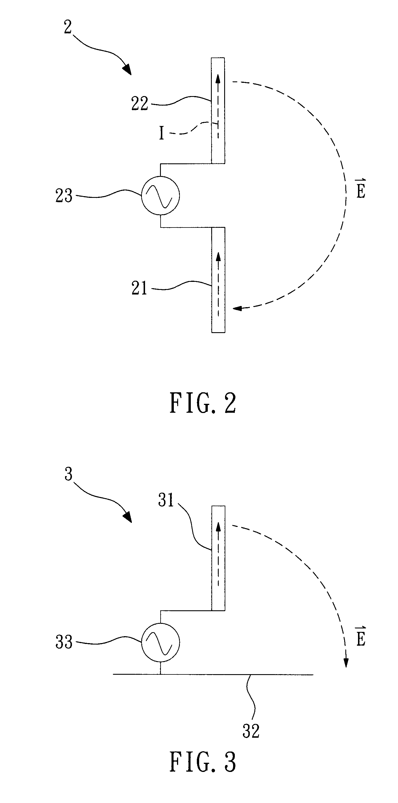
[0020]FIG. 2 is a schematic diagram of a dipole antenna. The dipole antenna 2 has two support arms 21, 22 that are each connected to a power supply 23, and a current I flows through the support arms 21, 22 to form an electric field {right arrow over (E)}, so as to produce electromagnetic wave radiation.

[0021]FIG. 3 is a schematic diagram of a monopole antenna. In order to reduce the volume of the antenna and to construct the antenna conveniently, one of the support arms of the dipole antenna is replaced with a metal plate, so that the dipole antenna is simplified into a monopole antenna 3. The monopole antenna 3 has a support arm 31 and a metal plate 32, in which the support arm 31 is perpendicular to the metal plate 32. The support arm 31 and the metal plate 32 are each connected to a power supply 33, and a current I flows through the support arm 31 to form an electric field {right arrow over (E)}, thereby producing electromagnetic wave radiation.

[0022]The length of the monopole an...


PUM


Abstract

A radio frequency identification (RFID) tag using a monopole antenna is provided, in which an antenna structure is disposed on a metal plate, two ends of an RFID chip are electrically connected to the antenna structure, and the antenna structure and the RFID chip form a loop structure. The RFID tag can be disposed on a surface of an object to be measured, or disposed in an inner accommodation space of the object to be measured, so it is widely used in various applications. Additionally, the RFID tag is easily manufactured, so the production cost can be reduced. Furthermore, the RFID tag has a larger readable distance, and an electromagnetic wave emitting direction of the RFID tag is adjustable according to different included angles between the metal plate and the antenna structure, thereby causing signals to be read easily and identification ability to improve, two desirable effects.

Description

BACKGROUND OF THE INVENTION[0001]1. Field of the Invention[0002]The present invention relates to an identification tag, and more particularly to a radio frequency identification (RFID) tag using a monopole antenna.[0003]2. Description of the Related Art[0004]FIG. 1 is a schematic diagram of an RFID tag disclosed in U.S. Pat. No. 6,914,562. The conventional RFID tag 1 includes a packaging wall 11, two conductive tabs 12, an RFID device 13, and a radio frequency reflecting structure 14. The conductive tabs 12 and the RFID device 13 are disposed on a surface of the packaging wall 11, and the RFID device 13 is electrically connected to the conductive tabs 12. There are two feed points 15 and 16 between the RFID device 13 and the conductive tabs 12. The radio frequency reflecting structure 14 is disposed on the other surface of the packaging wall 11. In the conventional RFID tag 1, the radio frequency reflecting structure 14 is a metal plate.[0005]The impedance of the conventional RFID t...

Claims


Application Information

Patent Timeline
IPC IPC(8): G08B13/14
CPCG06K19/07749H01Q9/42H01Q1/2225
Inventor KUO, SHIH-KANGCHEN, SUNG-LINLIN, CHANG-TSUNLIAO, LUNG-CHI
Owner CHINA STEEL
Why Eureka
Try Eureka