Zirconia-carbon-containing refractory and method for producing same

Active Publication Date: 2009-09-17
KROSAKI HARIMA CORP
View PDF0 Cites 12 Cited by
  • Summary
  • Abstract
  • Description
  • Claims
  • Application Information

AI Technical Summary

Benefits of technology

[0012]Accordingly, it is a first object of the present invention to improve the corrosion resistance of a zirconia-carbon-containing refractory having a high ZrO2 content exceeding about 80% by mass. It is a second object of the present invention to also improve t

Problems solved by technology

The molten glass layer contains CaO, SiO2, Na2O, K2O, Al2O3, CaF2, C, and the like and is thus highly erosive to Al2O3, SiO2, C, and the like constituting the submerged nozzle, so that operation over long periods of time reduces the corrosion resistance of the submerged nozzle.
Meanwhile, a larger zirconia content increases the thermal expansion coefficient and the elastic modulus of the ZrO2—C material, disadvantageously causing breaks in use and hindering the operation.
As described above, however, an increas

Method used


Image

  • Zirconia-carbon-containing refractory and method for producing same
  • Zirconia-carbon-containing refractory and method for producing same
  • Zirconia-carbon-containing refractory and method for producing same

Examples


Example

Example B

[0131]Table 2 shows the quality of the zirconia-graphite materials containing various proportions of the graphite fine powder and carbon black having a diameter of 45 μm or less in the carbonaceous material excluding the bonding carbon.

[0132]In Comparative Examples 6 and 7 and Examples 8 to 11, the proportions of the carbonaceous material having a diameter of 45 μm or less in the carbonaceous material excluding the bonding carbon were changed from 0% to 100%. At each of the proportions of 0% and 35% in Comparative Examples 6 and 7, the total volume percent of the apparent porosity and the carbonaceous material was 43% or more. The corrosion resistance was reduced. In contrast, at each of the proportions of the graphite fine powder of 40%, 60%, and 100% in Examples 8 to 10, both corrosion resistance and thermal shock resistance were significantly improved and satisfactory. In Example 11, part of (10%) the graphite fine powder was replaced with carbon black. The structure wa...

Example

Example C

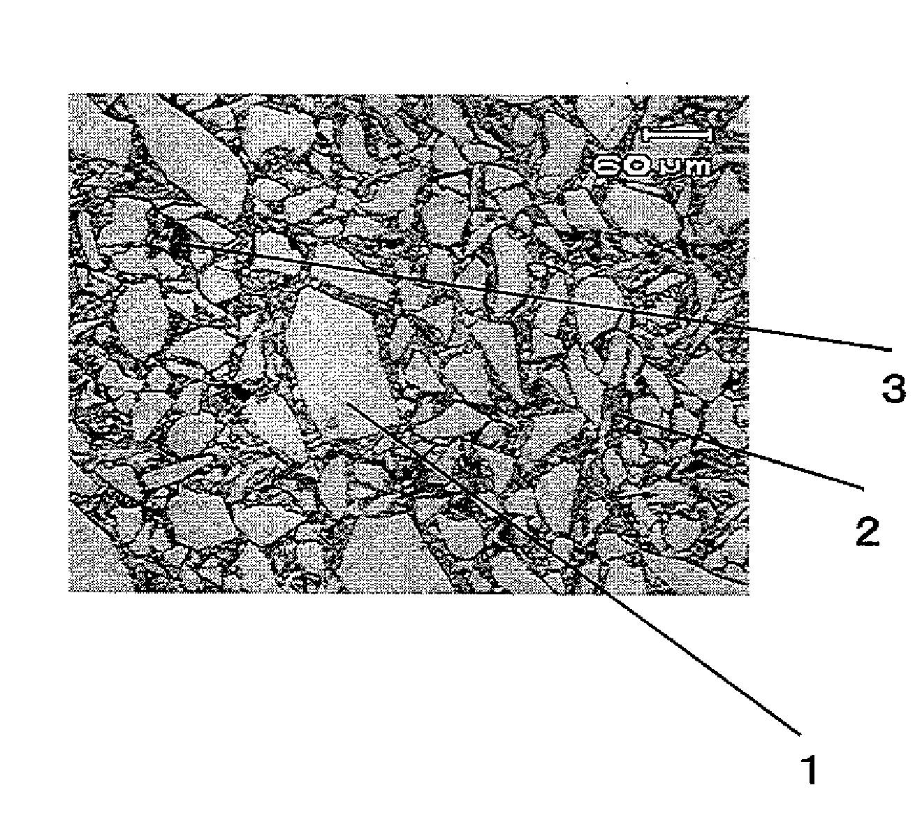
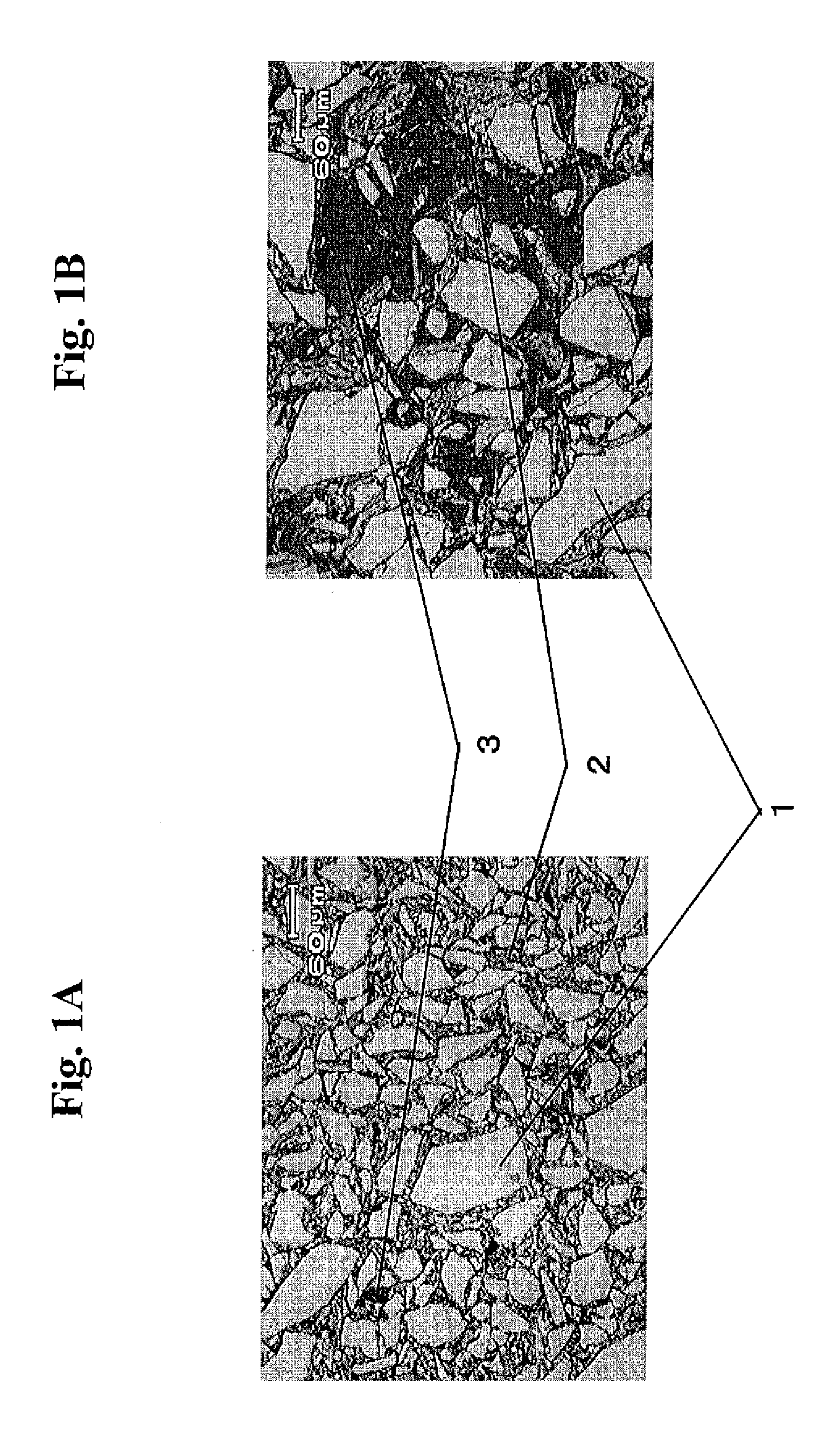
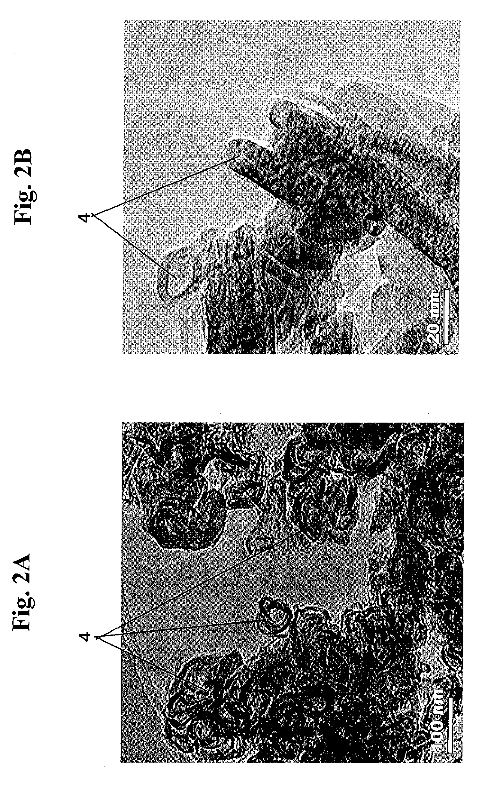
[0133]For zirconia-graphite materials having a ZrO2 content of 88% by mass so as to have improved corrosion resistance, in order to improve a reduction in wear resistance due to the increase in ZrO2 content, fine fibrous carbon structures were formed in the refractory matrix structures. Table 3 shows the results.

[0134]To form the fine fibrous carbon structures, a sol solution containing metallic Ni having a diameter of 30 nm was added in an amount of 0.2%, 0.5%, or 0.6% by mass in terms of metallic Ni. In Example 12 in which the Ni catalyst was not contained, the results demonstrated that although the corrosion resistance was satisfactory, the spall threshold temperature ΔT was 1,000° C., which was the lower limit. In each of Example 13 in which the amount of Ni added was 0.2% by mass and Example 14 in which Ni the amount of Ni added was 0.5% by mass, the corrosion resistance was satisfactory. Furthermore, the addition of the Ni catalyst improved the thermal shock resistanc...


PUM

PropertyMeasurementUnit
Lengthaaaaaaaaaa
Fractionaaaaaaaaaa
Fractionaaaaaaaaaa

Abstract

A zirconia-carbon-containing refractory includes aggregate grains, a carbon bond formed between the aggregate grains, 80% by mass or more of a ZrO2 component, and a carbonaceous material, in which the total volume of open pores and the carbonaceous material in the structure of the refractory is in the range of 25% to 42% by volume, open pores each having a diameter of 10 Am or more account for 30% or less of the total volume of open pores in the structure of the refractory, and carbonaceous material grains each having a maximum length exceeding 45 μm in the carbonaceous material in the zirconia-carbon-containing refractory account for less than 60% by mass of the total mass of the carbonaceous material except the bonding carbon in the zirconia-carbon-containing refractory.

Description

BACKGROUND OF THE INVENTION[0001]1. Field of the Invention[0002]The present invention relates to refractories used for submerged nozzles and the like for use in continuous casting of steel. In particular, the present invention relates to a zirconia-carbon-containing refractory having high corrosion resistance and high thermal shock resistance.[0003]2. Description of the Related Art[0004]A submerged nozzle for use in continuous casting of steel is used to transfer molten steel from a tundish to a mold. The submerged nozzle is used to prevent molten steel from coming into contact with air to inhibit oxidation of molten steel and used to charge molten steel into the mold while the flow of molten steel is adjusted. This results in the prevention of contamination of steel with slag layer floating on the surface of molten steel and nonmetallic inclusions in molten steel, thereby improving the quality of steel and ensuring the stability of operation. In general, a molten glass layer, refer...

Claims


Application Information

Patent Timeline
IPC IPC(8): B32B3/26B29C71/02
CPCB22D41/54C04B2235/9676C04B35/013C04B35/482C04B35/803C04B2235/3208C04B2235/40C04B2235/405C04B2235/424C04B2235/425C04B2235/5248C04B2235/5264C04B2235/5436C04B2235/5454C04B2235/77C04B2235/9607B82Y30/00Y10T428/249985Y10T428/249978Y10T428/24997Y10T428/249982Y10T428/249986C04B35/80B22D11/10
Inventor MORIKAWA, KATSUMIYOSHITSUGU, DAISUKE
Owner KROSAKI HARIMA CORP
Why Eureka
Try Eureka