Turbomachine control system

a control system and turbomachine technology, applied in the direction of turbine/propulsion fuel valves, mechanical devices, machines/engines, etc., can solve the problems of unsatisfactory solutions, large amount of hydraulic energy, and high cost of electromechanical actuators, and achieve the effect of simplifying maintenance operations

Active Publication Date: 2009-09-24
SAFRAN TRANSMISSION SYST
View PDF11 Cites 27 Cited by
  • Summary
  • Abstract
  • Description
  • Claims
  • Application Information

AI Technical Summary

Benefits of technology

[0019]Finally, it should be observed that the liquid flowing in the hydraulic circuit of the control system is not a specific liquid, but rather the fuel or the oil of the main circuit of the engine. This has the advantage of simplifying maintenance operations.

Problems solved by technology

Furthermore, the use of electromechanical actuators generally constitutes a solution that is more expensive.
The drawback of such an installation lies in the fact that the high pressure pump 18 is driven by the accessory gearbox 22 of the turbojet, such that the hydraulic energy generated by the high pressure pump 18 depends on the speed of rotation of the drive shaft of the turbojet.
Unfortunately, it is sometimes necessary to deliver a large amount of hydraulic energy to the actuators even at low speeds of rotation of the drive shaft of the turbojet.
Such a solution would be nevertheless unsatisfactory since the cylinder capacity of the high pressure pump 18 would then be much greater than required by the engine in its normal operating range.
Furthermore, such overdimensioning of the high pressure pump 18 would have the drawback of increasing its weight.
Another drawback stems from the fact that the high pressure pump 18 is heavily loaded and therefore heats up more than a standard high pressure pump (i.e. a pump dedicated solely to injecting fuel into the combustion chamber 20), and the fuel passing through the pump 18 is likewise heated.
This leads to the heat exchanger 17 cooling poorly.

Method used


Image

  • Turbomachine control system
  • Turbomachine control system
  • Turbomachine control system

Examples


Embodiment Construction

[0024]In the present application, the terms “upstream” and “downstream” are defined relative to the normal flow direction of the liquid (fuel or oil) in the circuit under consideration.

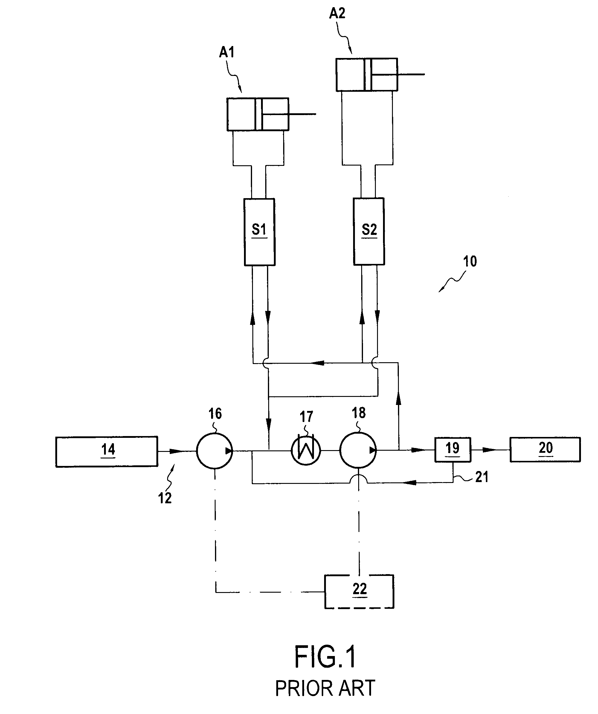
[0025]FIG. 1 shows the prior art and is described above.

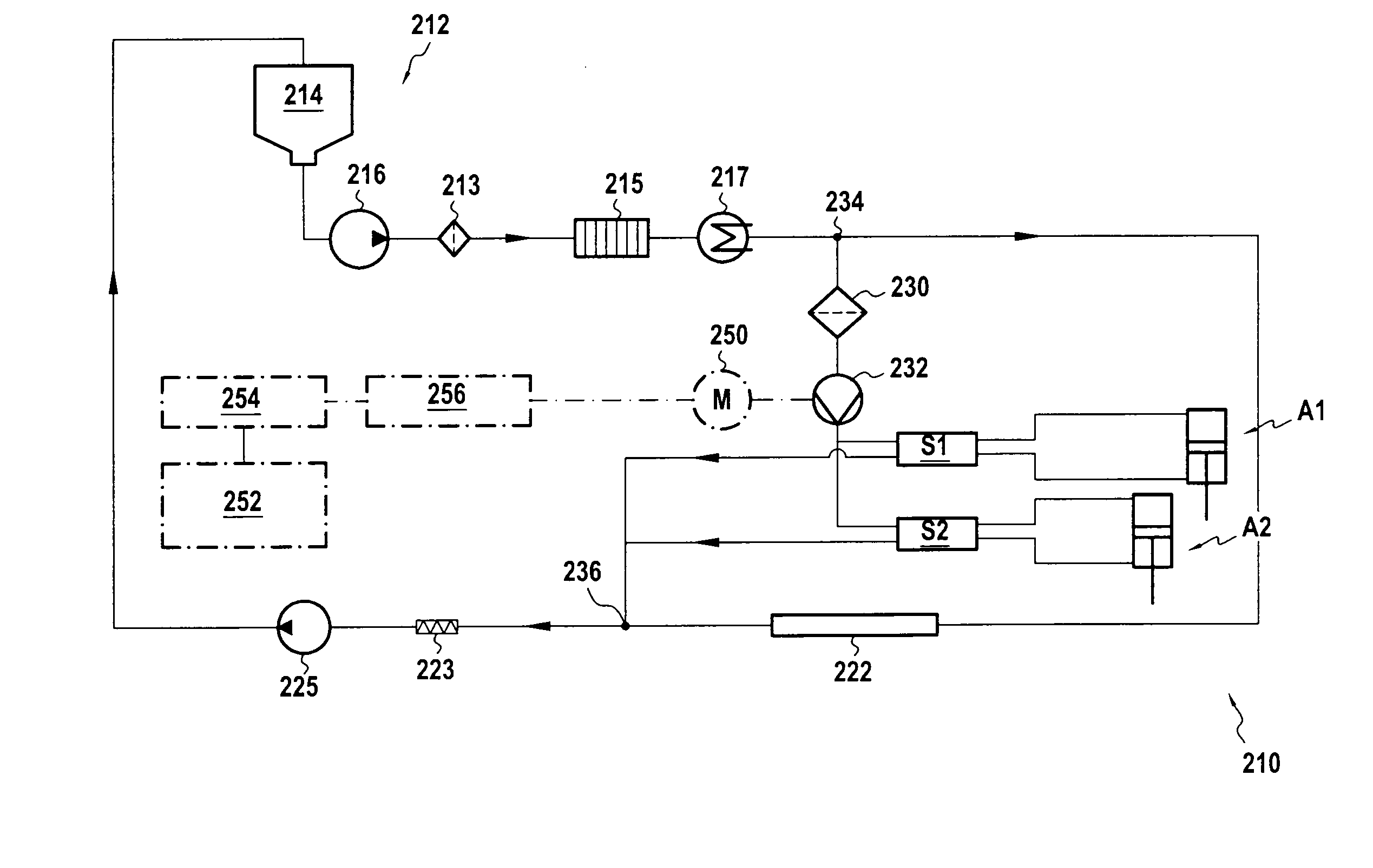
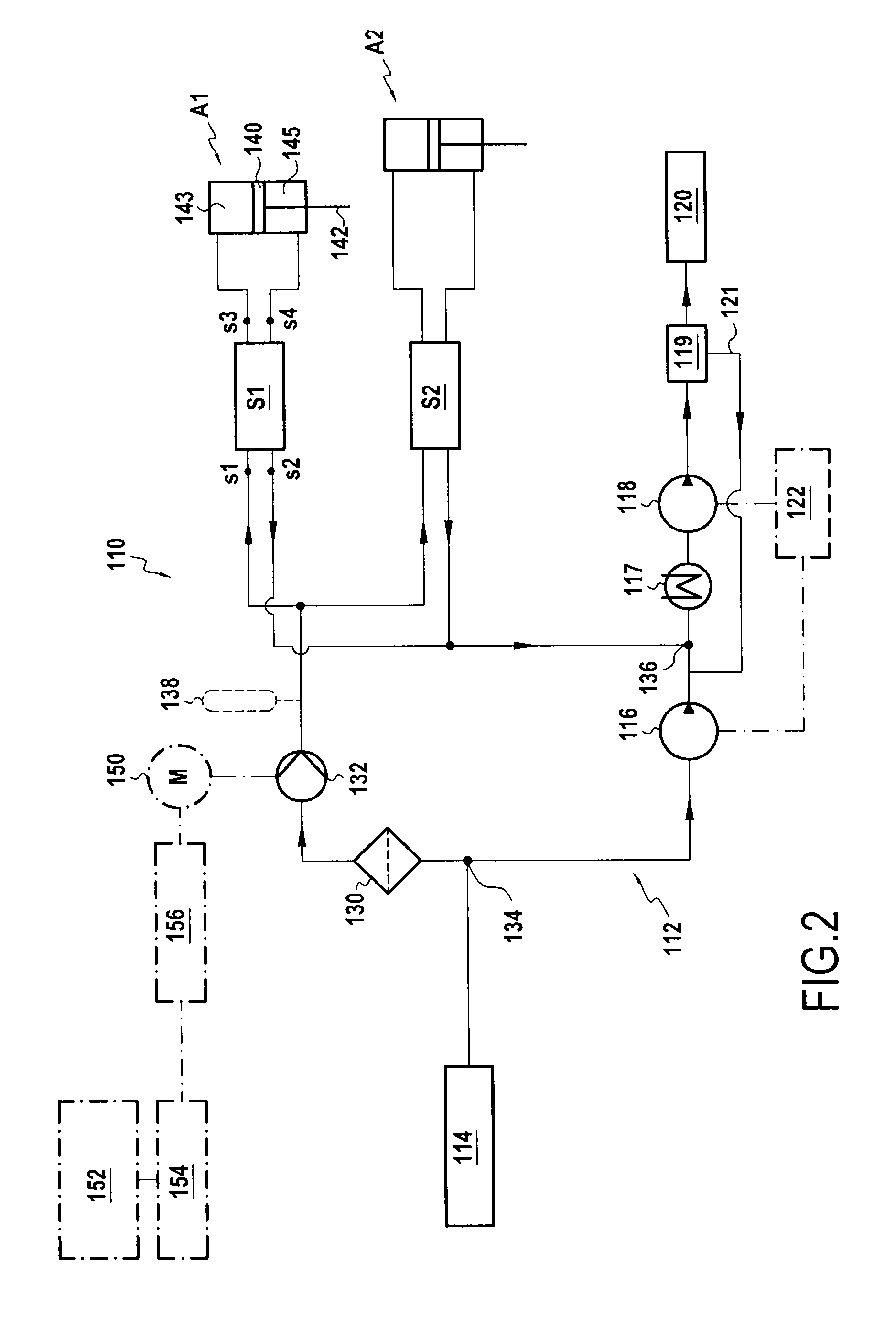
[0026]FIG. 2 shows the main fuel circuit 112 of an airplane turbojet. In the fuel flow direction, this circuit 112 comprises: a low pressure pump 116 connected to a fuel tank 114 (i.e. the airplane fuel tank); a heat exchanger 117; a high pressure pump 118; an HMU 119; and injectors for injecting fuel into the combustion chamber 120. The motors of the low pressure pump 116 and the high pressure pump 118 are driven by the accessory gearbox 122 of the turbojet. The low pressure pump 116 pumps the fuel from the tank 114, and the high pressure pump 118 feeds the fuel injectors of the combustion chamber 120 via the HMU 119. This HMU 119 serves in particular to measure out the fuel required by the combustion chamber 120, returning excess fuel to the ma...


PUM


Abstract

A turbomachine control system comprising an auxiliary hydraulic circuit with an auxiliary hydraulic pump, at least one hydraulic actuator, and at least one servo-valve, the auxiliary pump powering the actuator via the servo-valve. The auxiliary hydraulic circuit is connected in parallel with the main fuel or lubricating oil circuit of the turbomachine. Said auxiliary pump is driven by an electric motor.

Description

FIELD OF THE INVENTION[0001]The invention relates to a system for controlling a turbomachine. It is applicable to any type of turbomachine, whether for terrestrial or aviation purposes, and it is more particularly applicable to airplane turbojets.BACKGROUND OF THE INVENTION[0002]In the field of the invention, the term “control system” is used to designate a system that serves in particular to control the operating speed of the turbomachine. By way of example, in an airplane turbojet, the system controls the flow rate of air passing through the turbojet, the flow rate of fuel into the combustion chamber, etc.[0003]A control system generally comprises a plurality of actuators. By way of example, these actuators are air discharge valves or valves serving to adapt the geometry of the turbojet compressor.[0004]More precisely, the invention relates to a turbomachine control system comprising an auxiliary hydraulic circuit with at least one hydraulic actuator and at least one servo-valve, ...

Claims


Application Information

Patent Timeline
Patent Type & Authority Applications(United States)
IPC IPC(8): F02C7/00F02C7/22
CPCF02C7/232F02C7/236F05D2270/64F02C9/26F02C9/16
Inventor BOCQUET, DENIS LOUISSTUTZ, ANTOINE JEAN BAPTISTEMONTAROU, CEDRIC
Owner SAFRAN TRANSMISSION SYST
Why Eureka
Try Eureka