
Capacitive Ultrasonic Sensors and Display Devices Using the Same

Inactive Publication Date: 2009-09-24
IND TECH RES INST
View PDF10 Cites 62 Cited by
  • Summary
  • Abstract
  • Description
  • Claims
  • Application Information

AI Technical Summary

Benefits of technology

[0005]Examples of the present invention may provide a capacitive ultrasonic device capable of detecting an object and providing information regarding an orientation of the object, the capacitive ultrasonic device comprising a power source configured to generate a voltage signal, an array of sensor elements, each of the sensor elements being configured to generate an ultrasonic wave during a first period of the voltage signal and detect whether a wave is reflected from the object during a second period of the voltage signal when the voltage signal is applied thereto, and a control unit configured to activate a first portion of the array of sensor elements through the power source, and activate a second portion of the array of sensor elements when at least one of the first portion of the sensor elements detects a wave reflected from the object.

Problems solved by technology

These touch panels thus may not be user-friendly.
Furthermore, scratches or slurs resulting from an inappropriate force applied to the panel or a polluted input source may deteriorate the display quality of the panel.
Moreover, the touch panels may only support signal input at a two-dimensional (2D) plane, which may inappropriately limit the signal flexibility.
However, some non-touch panels may be disadvantageous in that the distance may be fixed and not flexible.
Furthermore, some non-touch panels may be liable to background light and may suffer from relatively low response speed.

Method used


Image

  • Capacitive Ultrasonic Sensors and Display Devices Using the Same
  • Capacitive Ultrasonic Sensors and Display Devices Using the Same
  • Capacitive Ultrasonic Sensors and Display Devices Using the Same

Examples


Embodiment Construction

[0022]Reference will now be made in detail to the present examples of the invention illustrated in the accompanying drawings. Wherever possible, the same reference numbers will be used throughout the drawings to refer to the same or like portions.

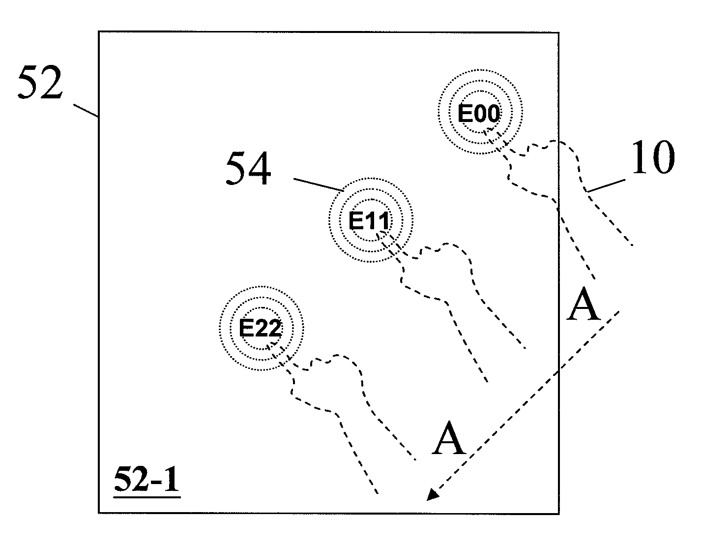
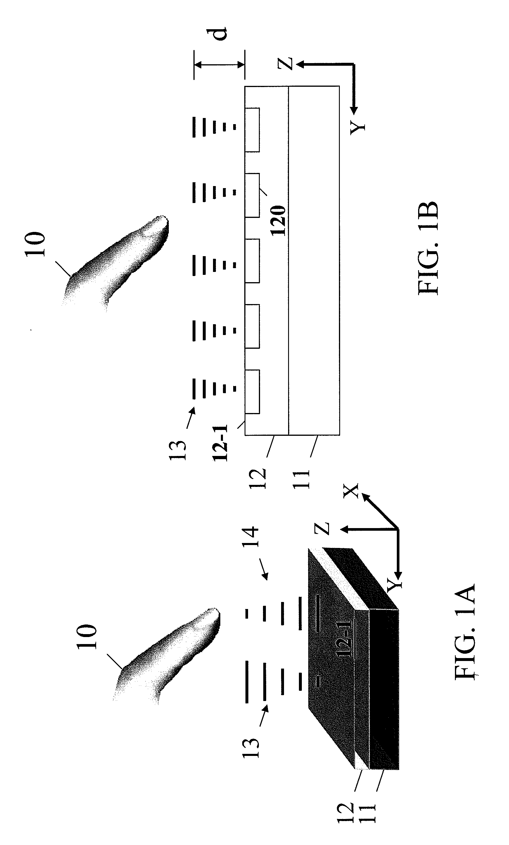
[0023]FIG. 1A is a schematic diagram of a capacitive ultrasonic sensor 12 in accordance with an example of the present invention. Referring to FIG. 1A, the capacitive ultrasonic sensor 12 may transmit ultrasonic waves 13 and receive reflected waves 14 reflected from an object 10. The capacitive ultrasonic sensor 12 may include a transparent membrane on which a plurality of sensor elements are formed. The capacitive ultrasonic sensor 12 may detect the movement of the object 10 based on the reflected waves 14 when the object 10 moves over the capacitive ultrasonic sensor 12 across a surface 12-1 thereof. Specifically, the capacitive ultrasonic sensor 12 may detect an orientation of the object 12, including a two-dimensional (2D) location of t...


PUM


Abstract

A capacitive ultrasonic device is capable of detecting an object and providing information regarding an orientation of the object. The capacitive ultrasonic device includes a power source configured to generate a voltage signal, an array of sensor elements, each of the sensor elements being configured to generate an ultrasonic wave during a first period of the voltage signal and detect whether a wave is reflected from the object during a second period of the voltage signal when the voltage signal is applied thereto, and a control unit configured to activate a first portion of the array of sensor elements through the power source, and activate a second portion of the array of sensor elements when at least one of the first portion of the sensor elements detects a wave reflected from the object.

Description

CROSS-REFERENCE TO RELATED APPLICATIONS[0001]This application contains subject matter related to the subject matters of the following applications, each of which is assigned to the same assignee as this application. The commonly assigned applications include U.S. patent application Ser. No. 11 / 212,611 (“the '611 application”), entitled “Method of Fabricating a Polymer-Based Capacitive Ultrasonic Transducer,” filed Aug. 29, 2005, U.S. patent application Ser. No. 11 / 703,910 (“the '910 application”), entitled “Flexible Capacitive Ultrasonic Transducer and Method of Fabricating the Same,” filed Feb. 7, 2007, and U.S. patent application Ser. No. 11 / 870,396 (“the '396 application”), entitled “Micro Ultrasonic Transducers,” filed Oct. 10, 2007, which is a continuation-in-part of U.S. patent application Ser. No. 10 / 648,495, filed Aug. 25, 2003, now abandoned.BACKGROUND OF THE INVENTION[0002]The present invention relates to capacitive ultrasonic transducers and, more particularly, to capacit...

Claims


Application Information

Patent Timeline
IPC IPC(8): G01B17/00
CPCG06F3/0416G06F2203/04101G06F3/043G06F3/0346G06F3/0436G06F3/04166
Inventor CHANG, MING-WEIDENG, HSU-CHENGGWO, TSUNG-JU
Owner IND TECH RES INST
Features
  • Generate Ideas
  • Intellectual Property
  • Life Sciences
  • Materials
  • Tech Scout
  • Unparalleled Data Quality
  • Higher Quality Content
  • 60% Fewer Hallucinations
Learn More