Magnetron

a magnet and magnetron technology, applied in the field of magnets, can solve the problems of increasing the risk of perforation, insufficient, serious consequences, etc., and achieve the effect of reducing the voltage stress

Active Publication Date: 2009-09-24
E2V TECH (UK) LTD
View PDF7 Cites 11 Cited by
  • Summary
  • Abstract
  • Description
  • Claims
  • Application Information

AI Technical Summary

Benefits of technology

[0010]The cover to the heater terminal on the cathode hides any sharp point, thereby reducing voltage stress.
[0011]The cover plate could be made of any conductor that is vacuum tube compatible. Nickel or a nickel alloy would be suitable because of its availability, ease of machining and ease of joining.

Problems solved by technology

Experience has shown that the cathode to end wall gap is not adequate to prevent arcing under all conditions (particularly when driven with line-type modulators) and very occasionally this can have serious consequences when the arcing causes the end wall to puncture.
The result is that the heater connection can form a seat for arcing, which can confine any arcing that occurs to the region of the wall 1 that is immediately adjacent, and thus increase the risk of perforation.
However, there are thousands of equipments currently in use, which require the current profile for the magnetron, so such a modification would be disadvantageous.
It is also undesirable to make anything more than the minimum change to the interior of the magnetron, as any change risks upsetting its operation.

Method used


Image

  • Magnetron
  • Magnetron
  • Magnetron

Examples


Embodiment Construction

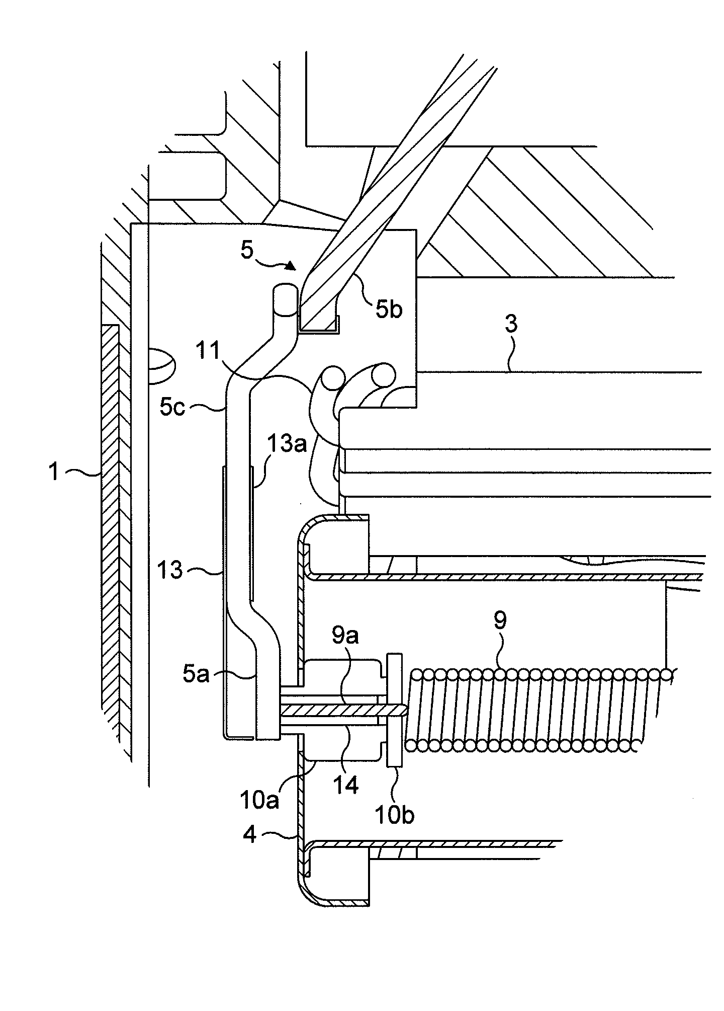
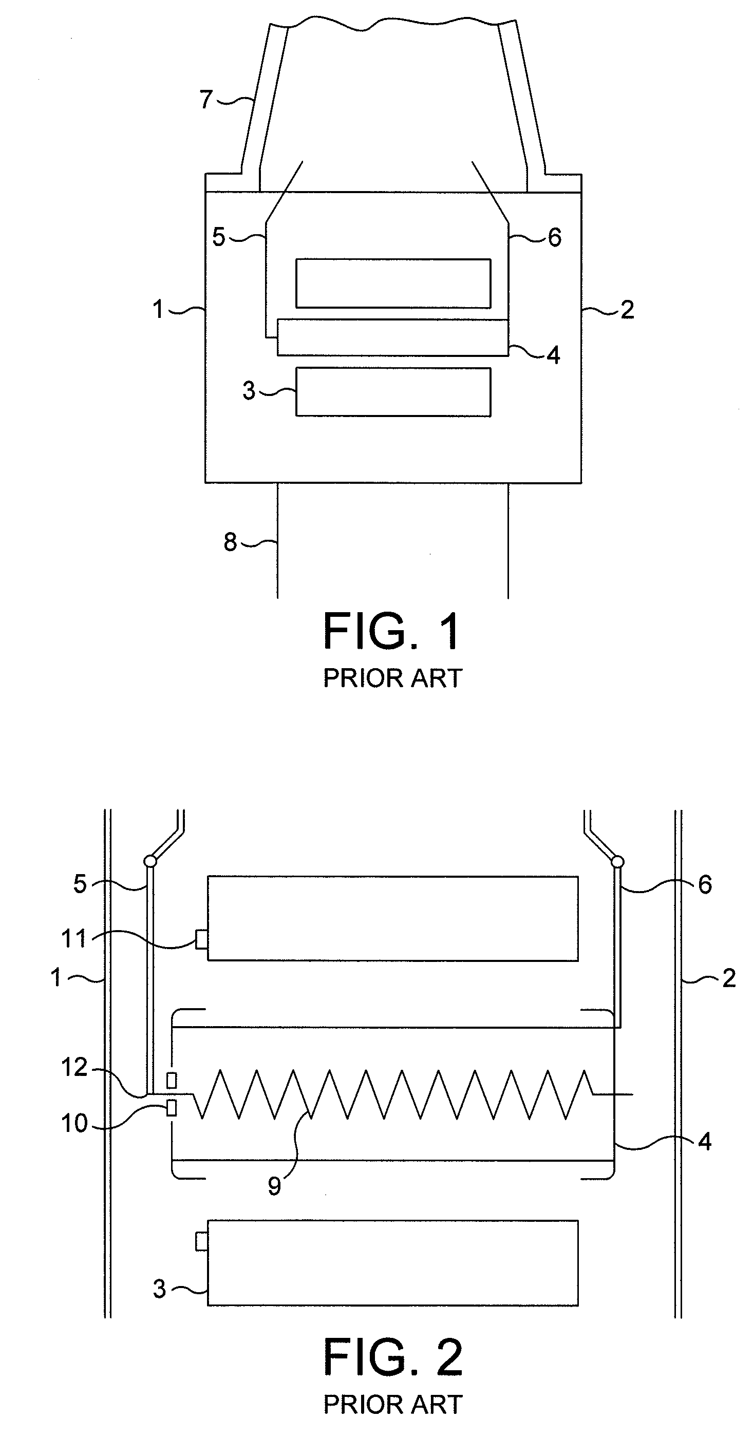
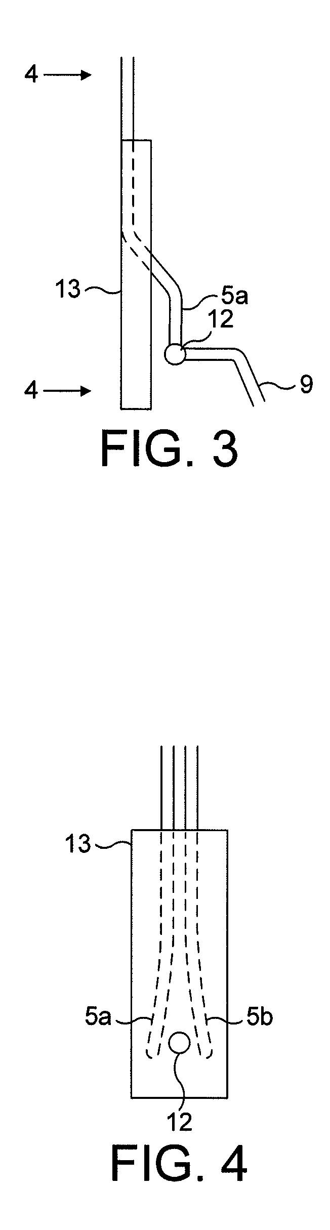
[0020]The invention can best be appreciated by considering FIGS. 3 and 4 in conjunction with FIG. 2, which show a modification made in accordance with the invention to the known magnetron. By comparing FIG. 3 with FIG. 2, it will be seen that, the support arm 5 is provided with a region 5a which is offset towards the cathode, so that the connection point 12 between the heater and the support arm 5 is displaced nearer to the cathode than in the prior art magnetron. In addition and in accordance with the invention, a cover 13 of conducting material is interposed between the connection point 12 and the adjacent end wall 1 of the vacuum chamber. The cover is made of nickel, or a nickel alloy, but other conducting materials could be used if desired. The region of the arm 5 over which the cover extends is in fact formed by two closely spaced conductors, which diverge in the region of connection point 12 to make the connection to the end of the heater easier. The upper end of the cover is ...


PUM


Abstract

A magnetron has an anode 3 surrounding a tubular hollow cathode 4 which contains a heater 9. The cathode is supported by radial arms at each end. At one end of the cathode, the heater is supplied with one terminal of its D.C. supply by means of a radial arm 5, which also serves to support that end of the cathode. The arm has a portion 5a offset towards the cathode, and a cover of conducting material is interposed between the heater connection and the adjacent end wall 1 of the vacuum envelope. The cover may have a folded portion so that it can be carried by the arm.

Description

CROSS-REFERENCE TO RELATED APPLICATIONS[0001]This application claims the priority of Great Britain Application No. 0805277.1, filed Mar. 20, 2008, the contents of which is incorporated herein by reference.BACKGROUND OF THE INVENTION[0002]This invention relates to magnetrons.[0003]A known magnetron will now be described with reference to FIGS. 1 and 2 of the drawings. FIG. 1 is a fragmentary sectional view of the magnetron, taken through the axis of the anode, and FIG. 2 is an enlarged view of the anode and cathode shown in FIG. 1. Referring to FIG. 1, the magnetron comprises a vacuum chamber having end walls 1 and 2, which are at right angles to the axis of the anode 3 and cathode 4 of the magnetron. There are resonant cavities (not shown) defined in the anode, or by vanes. A magnetic field is applied normal to the plane of the end walls 1,2, by an electromagnet or a permanent magnet (not shown).[0004]The cathode 4 is tubular, and has a heater extending along its axis, and a D.C. su...

Claims


Application Information

Patent Timeline
Patent Type & Authority Applications(United States)
IPC IPC(8): H01J25/50
CPCH01J25/50H01J23/05
Inventor WILSON, ROBERT CHARLES
Owner E2V TECH (UK) LTD
Why Eureka
Try Eureka