Adaptive focusing using liquid crystal zone plates in electro-optical readers

a technology of electro-optical readers and liquid crystal zones, which is applied in the direction of camera focusing arrangement, printers, instruments, etc., can solve the problems of consuming electrical power, noisy, noisy, etc., and achieve the effect of reducing noise, vibration and dust, size, weight, power and volume requirements, and reducing noise and vibration and dus

a technology of electro-optical readers and liquid crystal zones, which is applied in the direction of camera focusing arrangement, printers, instruments, etc., can solve the problems of consuming electrical power, noisy, noisy, etc., and achieve the effect of reducing noise, vibration and dust, size, weight, power and volume requirements, and reducing noise and vibration and dus

US20090237575A1Active Publication Date: 2009-09-24SYMBOL TECH LLC

Image

  • Adaptive focusing using liquid crystal zone plates in electro-optical readers
  • Adaptive focusing using liquid crystal zone plates in electro-optical readers
  • Adaptive focusing using liquid crystal zone plates in electro-optical readers

Examples


Embodiment Construction

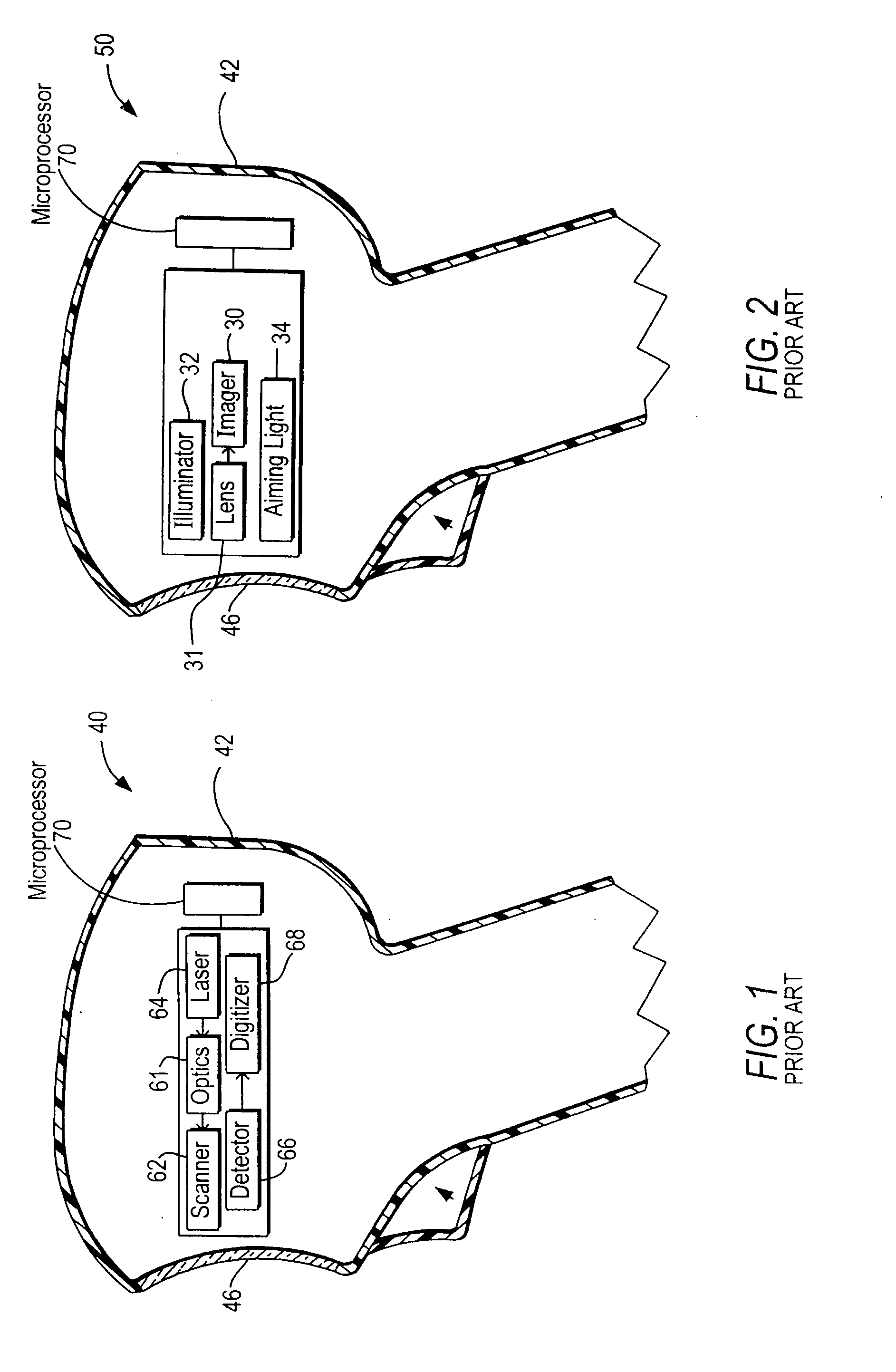
[0021]FIG. 1 depicts a conventional moving laser beam reader 40 for electro-optically reading indicia, such as a symbol, that may use, and benefit from, the present invention. The beam reader 40 includes a scanner 62 in a housing 42 for scanning an outgoing laser beam from a laser 64 and / or a field of view of a light detector or photodiode 66 in a scan pattern, typically comprised of one or more scan lines, through a window 46 across the symbol for reflection or scattering therefrom as return light detected by the photodiode 66 during reading. The beam reader 40 also includes a focusing lens assembly or optics 61 for optically modifying the outgoing laser beam to have a large depth of field, and a digitizer 68 for converting an electrical analog signal generated by the detector 66 from the return light into a digital signal for subsequent decoding by a microprocessor or controller 70 into data indicative of the symbol being read.

[0022]FIG. 2 depicts a conventional imaging reader 50 ...


PUM

PropertyMeasurementUnit
timeaaaaaaaaaa
optical index of refractionaaaaaaaaaa
index of refractionaaaaaaaaaa

Abstract

Working range and beam cross-section are adjusted in an electro-optical reader for reading indicia by applying voltages to electrodes in one or more liquid crystal zone plates in which the index of refraction is changed in different regions of each zone plate.

Description

[0001]Solid-state imaging systems or imaging readers, as well as moving laser beam readers or laser scanners, have both been used to electro-optically read one-dimensional bar code symbols, particularly of the Universal Product Code (UPC) type, each having a row of bars and spaces spaced apart along one direction, and two-dimensional symbols, such as Code 49, which introduced the concept of vertically stacking a plurality of rows of bar and space patterns in a single symbol. The structure of Code 49 is described in U.S. Pat. No. 4,794,239. Another two-dimensional code structure for increasing the amount of data that can be represented or stored on a given amount of surface area is known as PDF417 and is described in U.S. Pat. No. 5,304,786.DESCRIPTION OF THE RELATED ART[0002]The imaging reader includes a solid-state imager or sensor having an array of cells or photosensors, which correspond to image elements or pixels in a field of view of the imager, and an imaging lens assembly fo...

Claims


Application Information

Patent Timeline
24 Sep 2009
Publication
US20090237575A1
IPC
G02F1/13
CPC
G02B3/14; G02F1/134309; G06K7/10831; G02F2001/294; G06K7/10811; G02F1/29; G02F1/294
Inventors
TSI-SHI, DAVID