Adaptive focusing using liquid crystal lens in electro-optical readers

Inactive Publication Date: 2009-07-02
SYMBOL TECH INC
View PDF11 Cites 47 Cited by
  • Summary
  • Abstract
  • Description
  • Claims
  • Application Information

AI Technical Summary

Benefits of technology

[0013]The changing between different focal planes, different imaging planes, and / or the changing of the light cross-section is performed without mechanically or physically moving solid lenses, thereby decreasing the noise and vibration and dust in such readers, as well as the size, weight, power and volume requirements. The variable LC lens will not wear out over time.

Problems solved by technology

This is disadvantageous for several reasons.
First, the mechanical movement generates vibrations that are propagated through the reader to a user's hand in a handheld mode of operation, and may also generate dust to obscure the lens assembly.
Moreover, the vibrations can generate objectionable, annoying, audible hum.
In addition, the lens movement requires a drive that, in turn, consumes electrical power, is expensive and slow, can be unreliable, occupies space and increases the overall weight, size and complexity of the reader.
The liquid lens, however, has an unpredictable, nonlinear, curved transfer function and, in practice, exhibits a hysteresis property, in which the transfer function for increasing applied voltages is different from the transfer function for decreasing applied voltages.
However, the known LC cells are not entirely uniform or homogeneous and undesirably scatter light, thereby producing a non-uniform optical response.

Method used


Image

  • Adaptive focusing using liquid crystal lens in electro-optical readers
  • Adaptive focusing using liquid crystal lens in electro-optical readers
  • Adaptive focusing using liquid crystal lens in electro-optical readers

Examples


Embodiment Construction

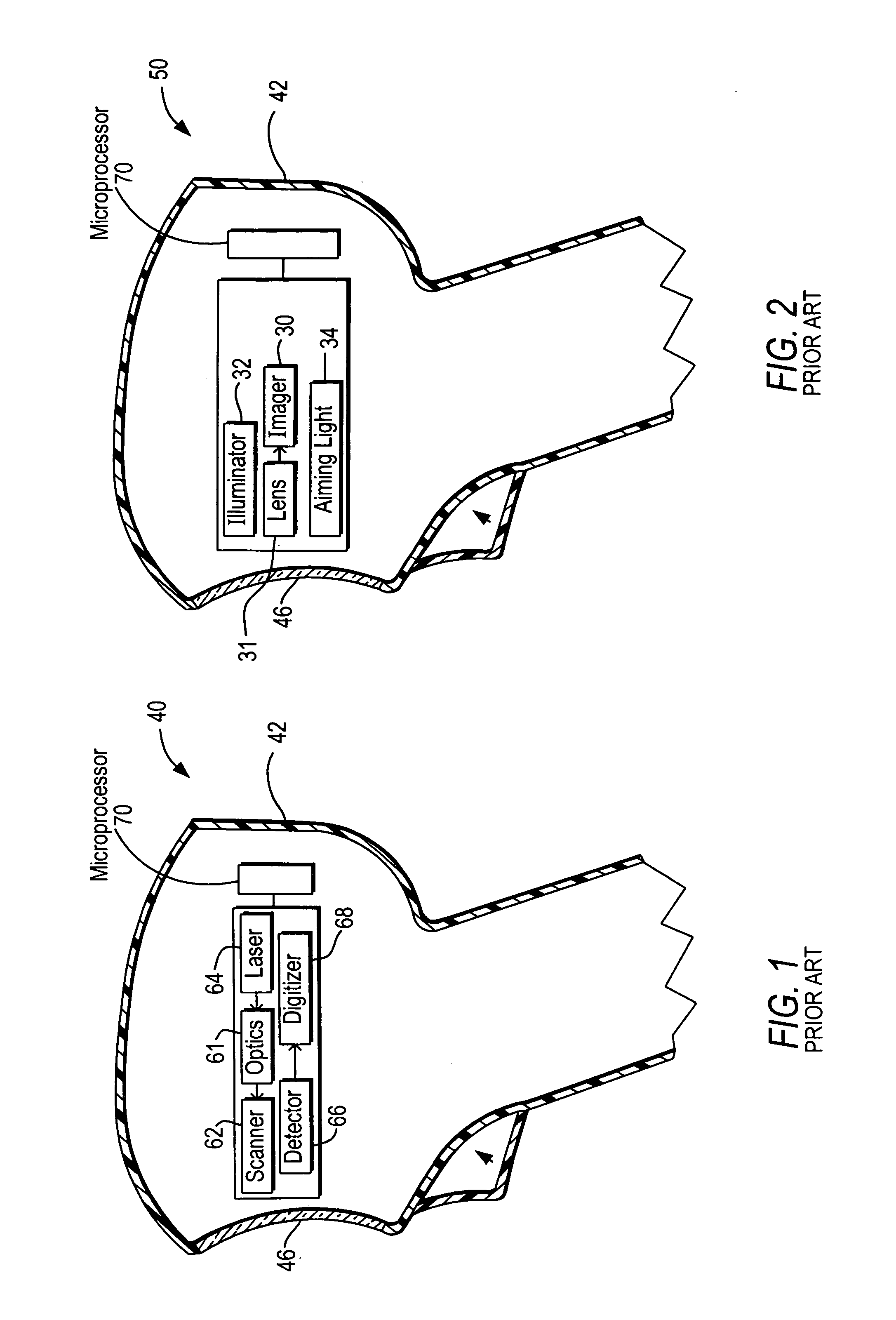
[0025]FIG. 1 depicts a conventional moving laser beam reader 40 for electro-optically reading indicia, such as a symbol, that may use, and benefit from, the present invention. The beam reader 40 includes a scanner 62 in a housing 42 for scanning an outgoing laser beam from a laser 64 and / or a field of view of a light detector or photodiode 66 in a scan pattern, typically comprised of one or more scan lines, through a window 46 across the symbol for reflection or scattering therefrom as return light detected by the photodiode 66 during reading. The beam reader 40 also includes a focusing lens assembly or optics 61 for optically modifying the outgoing laser beam to have a large depth of field, and a digitizer 68 for converting an electrical analog signal generated by the detector 66 from the return light into a digital signal for subsequent decoding by a microprocessor or controller 70 into data indicative of the symbol being read.

[0026]FIG. 2 depicts a conventional imaging reader 50 ...


PUM


Abstract

Working range and beam cross-section are adjusted in an electro-optical reader for reading indicia by applying voltages to electrodes in one or more liquid crystal lenses in which the index of refraction is changed.

Description

DESCRIPTION OF THE RELATED ART[0001]Solid-state imaging systems or imaging readers, as well as moving laser beam readers or laser scanners, have both been used to electro-optically read one-dimensional bar code symbols, particularly of the Universal Product Code (UPC) type, each having a row of bars and spaces spaced apart along one direction, and two-dimensional symbols, such as Code 49, which introduced the concept of vertically stacking a plurality of rows of bar and space patterns in a single symbol. The structure of Code 49 is described in U.S. Pat. No. 4,794,239. Another two-dimensional code structure for increasing the amount of data that can be represented or stored on a given amount of surface area is known as PDF417 and is described in U.S. Pat. No. 5,304,786.[0002]The imaging reader includes a solid-state imager or sensor having an array of cells or photosensors, which correspond to image elements or pixels in a field of view of the imager, and an imaging lens assembly fo...

Claims


Application Information

Patent Timeline
IPC IPC(8): G02F1/1333
CPCG02F1/134309G02F1/13471G06K7/10831G02F2203/28G06K7/10792G02F1/29
Inventor VINOGRADOV, IGORTAN, CHINH
Owner SYMBOL TECH INC
Why Eureka
Try Eureka