Battery

a battery and battery technology, applied in the field of batteries, can solve the problems of battery capacity falling, battery being unable to give a high power, battery deterioration, etc., and achieve the effects of reducing production costs, facilitating catalytic effect effective, and facilitating production

Active Publication Date: 2009-09-24
OHARA
View PDF4 Cites 33 Cited by
  • Summary
  • Abstract
  • Description
  • Claims
  • Application Information

AI Technical Summary

Benefits of technology

[0055]In the catalytic material, more advantageous effects are produced by making the specific surface area of the positive electrode large by use of fine particles; therefore, as for the linear diameter of the particles, the smaller the better. Thus, the aspect ratio is preferably 100 or less, more preferably 90 or less, and most preferably 80 or less. The aspect ratio is obtained as follows: a particle is sandwiched between two parallel straight lines along various directions; when the distance between the two lines is maximum, the distance is represented by D; when the distance therebetween is minimum, the distance is represented by d; the ratio of D / d is calculated; about the particle and other particles, the number (n) of which is 30 or more, the average of the ratios of D / d is calculated; and the resultant is defined as the aspect ratio.
[0056]FIG. 6 illustrates an aspect of the structure (ii). In FIG. 6, a current collecting unit 9 is made of a skeleton material 91, and at least a part thereof is coated with a catalytic material 93 having electron conductivity. When the catalytic material itself is caused to have a current collecting function in this way, the production of the battery can be made effective. Since Au, Pt, Ni or some other catalytic material has seawater resistance, it is preferred to use such a catalytic material to attain the coating.
[0057]When the surface form of the catalytic material used for coating is made into a needle form, the surface area thereof is made large so that the material can favorably give catalytic effect effectively.
[0058]FIG. 7 is a view illustrating an aspect of the structure (ii). In FIG. 7, a current collecting unit 94(9) has a skeleton made of a catalytic material, and the skeleton itself acts as a catalyst and further has a current collecting function. By causing the skeleton itself to act as a catalyst and further have a current collecting function in this way, the production can be made efficient. Since Au, Pt, Ni or some other catalytic material has seawater resistance, it is preferred to use such a catalytic material.
[0059]In the positive electrode having the above-mentioned structure in the invention, the lower limit of the thickness thereof is preferably 10 μm, more preferably 20 μm, and most preferably 30 μm in order for the positive electrode to hold the liquid functioning as both of an active material and an electrolyte in a sufficient amount to make the electrode reaction area large. The upper limit of the thickness is preferably 20 mm, more preferably 10 mm, and most preferably 5 mm since liquid fluidity is required inside the electrode in order to promote the battery reaction.
[0060]The negative electrode in the battery of the invention is preferably made of metallic lithium or a lithium alloy since the output energy per unit volume can be made large. The thickness of the lithium metal or lithium alloy is preferably 0.02 mm or more, more preferably 0.03 mm or more, and most preferably 0.05 mm or more.

Problems solved by technology

Such a structure has a problem that when the inorganic solid electrolyte contacts the positive electrode for a long term, a deterioration is generated in the interface between the inorganic solid electrolyte and the positive electrode so that the battery capacity comes to fall or the battery comes to be unable to give a high power.

Method used


Image

  • Battery
  • Battery
  • Battery

Examples


example 1

[0076][Formation of an Electrolyte Substrate]

[0077]As raw materials, the following were used: H3PO4, Al(OH)3, and Li2CO3 manufactured by Nippon Chemical Industrial Co., Ltd.; SiO2 manufactured by Nitchitsu Co., Ltd.; TiO2 manufactured by Sakai Chemical Industry Co., Ltd.; GeO2 manufactured by Sumitomo Metal Mining Co., Ltd.; and ZrO2 manufactured by Nippon Denko. These were weighed to set the composition thereof as follows: P2O5=37.5%, Al2O3=7.5%, Li2O=14.5%, SiO2=1.3%, TiO2=17.5%, GeO2=20.2%, and ZrO2=1.5% wherein each of the symbols “%” herein denotes % by mol. The components were mixed into a homogeneous state. Thereafter, the components were put into a platinum crucible, and then heated and melted in an electric furnace. At this time, the starting material was first decomposed at 700° C. to vaporize CO2 and H2O components. Next, the remaining material was heated to 1400° C., and melted at the temperature for 1.5 hours. Thereafter, the melted glass was cast onto an iron plate war...

example 2

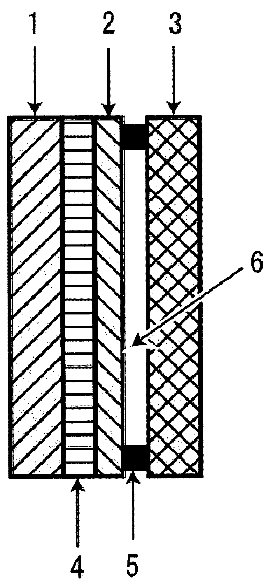
[0080]A battery was formed in the same way as in Example 1 except that the following were laminated onto each other: a doughnut-shaped PTFE having a thickness of 5 mm and an opening of 15 mm diameter, as a spacer; and a Ni mesh (thickness: 0.1 mm, diameter: 16 mm, line diameter: 0.05 mm, mesh size: 100 mesh / inch), as a positive electrode.

example 3

[0081]A battery was formed in the same way as in Example 1 except that a doughnut-shaped PTFE having a thickness of 2 mm and an opening of 15 mm diameter was used as a spacer, and further a Pt mesh (thickness: 0.14 mm, diameter: 16 mm, line diameter: 0.07 mm, mesh size: 100 mesh / inch) was used as a positive electrode.


PUM

PropertyMeasurementUnit
porosityaaaaaaaaaa
porosityaaaaaaaaaa
particle diameteraaaaaaaaaa

Abstract

To solve a problem that in a battery having a negative electrode having a capability of releasing a metal ion, a positive electrode for causing a liquid such as water or seawater to contribute to battery reaction, and an inorganic solid electrolyte, the inorganic solid electrolyte contacts the positive electrode for a long term, whereby a deterioration is generated from the interface between the electrolyte and the positive electrode so that the battery capacity falls or the battery cannot give a high power. The positive electrode and the inorganic solid electrolyte are not brought into contact with each other. Preferably, the interval between the positive electrode and the electrolyte is set to 0.3 nm or more.

Description

CROSS REFERENCES TO RELATED APPLICATIONS[0001]The present application claims priority under 35 U.S.C. §119 from Japanese Patent Application No. 2008-070702 filed with the Japan Patent Office on Mar. 19, 2008, the entire contents of which are incorporated herein by reference.BACKGROUND OF THE INVENTION[0002]1. Field of the Invention[0003]The present invention relates to a battery, and more specifically to a battery having a negative electrode having a capability of releasing a metal ion, a positive electrode for causing a liquid such as water or seawater to contribute to battery reaction, and an inorganic solid electrolyte.[0004]2. Description of the Related Art[0005]Batteries as described above are disclosed, for example, as lithium / water batteries in Patent Document 1 described below. Such a battery has a structure composed of a negative electrode (made of, for example, Li metal), a protective layer, a solid electrolyte, and a positive electrode. In general, the positive electrode ...

Claims


Application Information

Patent Timeline
Patent Type & Authority Applications(United States)
IPC IPC(8): H01M6/18H01M4/02H01M4/58H01M2/16H01M2/18H01M4/06H01M4/40H01M4/66H01M6/26
CPCH01M4/40H01M4/92Y02E60/50H01M6/34H01M2300/0071H01M6/32
Inventor KATOH, TAKASHI
Owner OHARA
Why Eureka
Try Eureka