Control device and control method for vehicle

a control device and control method technology, applied in fluid gearings, instruments, gearings, etc., can solve the problems of inability to satisfy the acceleration feeling of the driver, the torque converter is not able to transmit 100 percent of input-side power to the output side, and the driver may feel it as poor drivability, so as to prevent the driver's uncomfortable feeling and reduce the engine rotational speed

Inactive Publication Date: 2009-09-24
TOYOTA JIDOSHA KK
View PDF0 Cites 15 Cited by
  • Summary
  • Abstract
  • Description
  • Claims
  • Application Information

AI Technical Summary

Benefits of technology

[0032]According to the aspects of the invention, it is possible to provide a control device and control method for a vehicle, which is able to synchronize a decrease in engine rotational speed due to shifting with a decrease in en

Problems solved by technology

Thus, it is difficult to satisfy the acceleration feeling of the driver who wants to increase the vehicle speed with an increase in engine rotational speed.
Because of the above mechanism, the torque converter is not able to transmit 100 percent of input-side power to the output side when power of the engine is transmitted to the transmission mechanism by hydraulic oil, because of a friction or a slip between the hydraulic oil

Method used


Image

  • Control device and control method for vehicle
  • Control device and control method for vehicle
  • Control device and control method for vehicle

Examples


Embodiment Construction

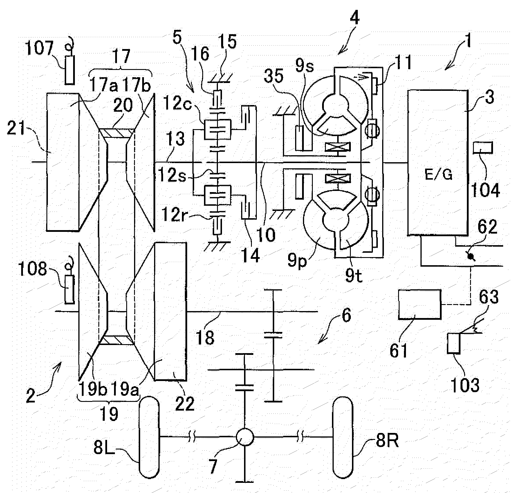
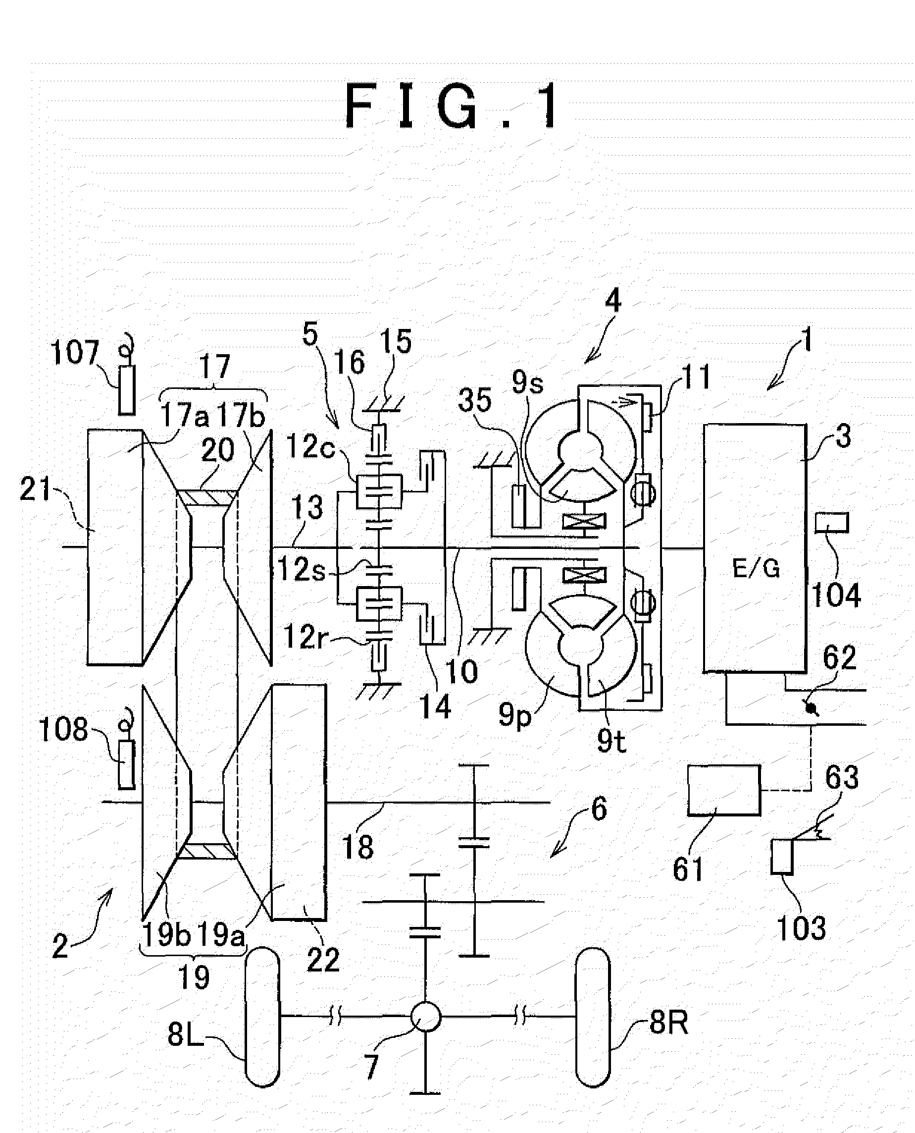
[0041]Hereinafter, an embodiment of the invention will be described with reference to the accompanying drawings. First, the configuration of the embodiment will be described. FIG. 1 is a schematic block diagram of a vehicle power transmission system with a continuously variable transmission according to the embodiment of the invention.

[0042]As shown in FIG. 1, a power transmission system 1 is, for example, applied to a transversely mounted front-engine front-drive (FF) vehicle, and includes a belt-type continuously variable transmission 2 and an engine 3, which is an internal combustion engine.

[0043]The output of the engine 3 is transmitted from a torque converter 4 through a forward-reverse switching device 5, the belt-type continuously variable transmission (hereinafter, simply referred to as “CVT”) 2 and a reduction gear 6 to a differential gear unit 7, and then distributed to left and right driving wheels 8L and 8R. That is, the CVT 2 is provided in a power transmission path fro...


PUM


Abstract

By shifting a lock-up clutch of a torque converter from a released state into an engaged state on condition that a gear ratio of an input shaft of a CVT to an output shaft of the CVT is decreasing (upshift), a lock-up control at the time of an increase in vehicle speed is performed while the gear ratio is being changed in a stepped manner. Thus, it is possible to synchronize a decrease in engine rotational speed due to shifting with a decrease in engine rotational speed due to lock-up engagement. Hence, lock-up engagement may be performed so that the driver does not recognize a decrease in engine rotational speed due to the lock-up engagement and, as a result, it is possible to prevent driver's uncomfortable feeling.

Description

INCORPORATION BY REFERENCE[0001]The disclosure of Japanese Patent Application No. 2008-074140 filed on Mar. 21, 2008 including the specification, drawings and abstract is incorporated herein by reference in its entirety.BACKGROUND OF THE INVENTION[0002]1. Field of the Invention[0003]The invention relates to a control device and control method for a vehicle equipped with a lock-up torque converter and a transmission.[0004]2. Description of the Related Art[0005]In recent years, automatic transmission (AT) vehicles (AT vehicles) that automate gear shiftings and clutch operations required for manual transmission (MT) vehicles (MT vehicles) have been increasing, and it is said that the percentage of AT vehicles exceeds 90 percent of commercially available vehicles.[0006]The AT mechanism includes a torque converter and a transmission mechanism. The torque converter utilizes the flow of fluid, such as hydraulic oil (oil), to transmit power from a power source (engine or electric motor) to ...

Claims


Application Information

Patent Timeline
IPC IPC(8): F16H61/14F16H47/06G06F17/00
CPCF16H61/143Y10T477/6197F16H2061/6615
Inventor TAWARA, MASAHIROTSUJITA, MASAYUKI
Owner TOYOTA JIDOSHA KK
Why Eureka
Try Eureka