Subsonic and stationary ramjet engines

a ramjet and subsonic technology, applied in the field of power plants, can solve the problems of consuming a great deal of fuel by flying supersonically, ramjets have virtually no commercial applications, and generate shockwaves and shockwaves. waste energy, waste energy, etc., to achieve high efficiency, eliminate wasteful drag, and high energy flow

Inactive Publication Date: 2009-10-01
AMICABLE INVENTIONS LLC
View PDF49 Cites 12 Cited by
  • Summary
  • Abstract
  • Description
  • Claims
  • Application Information

AI Technical Summary

Benefits of technology

[0010]In light of the above-described issues with current ramjet engines, it is an object of some of the preferred embodiments of the present invention to show how to run a stationary ramjet engine to obtain mechanical power. Further, some disclosed embodiments of the present invention will show how to replace a de Laval nozzle with a supersonic to subsonic convertor which does not have a choke area. Some embodiments of the present invention, even further, will show how to generate nearly or approximately adiabatically from the same atmosphere the high energy flows of air and other gas which let the ramjet engine operate at high efficiency. The term “adiabat

Problems solved by technology

Ramjet engines have been around for 50 years, and are famous for high efficiency, yet, today, ramjets have virtually no commercial applications other than military.
Supersonic speed generates shockwaves and shockwaves waste energy.
Unless an aircraft flies at very high altitude where air is much less dense, it will consume a great deal of fuel by flying supersonically.
So there is little economic demand for commercial supersonic aircraft.
But there is some demand, and it is not being met by ramjet engines even though they are much more efficient than turbine engines.
And that is a problem.
It

Method used


Image

  • Subsonic and stationary ramjet engines
  • Subsonic and stationary ramjet engines
  • Subsonic and stationary ramjet engines

Examples


Embodiment Construction

[0024]Reference will now be made in detail to various exemplary embodiments of the invention. The following detailed description is presented for the purpose of describing certain embodiments in detail and is, thus, not to be considered as limiting the invention to the embodiments described. Rather, the true scope of the invention is defined by the claims.

[0025]Temperatures herein are generally expressed in absolute degrees Kelvin, sometimes in degrees Centigrade, and room temperature is approximately 294 K. Atmospheric air or gas is air or gas at ambient pressure and temperature. If atmospheric temperature is T0 K, and that air or gas is adiabatically changed to have a stagnation temperature of Ts K by some means, this result is referred to herein as “high energy” air or gas if the stagnation temperature Ts K is 3 times T0 K or higher. High energy air / gas has a specific energy approximately Ts / T0 times the specific energy of the air / gas at atmospheric conditions of temperature and ...


PUM


Abstract

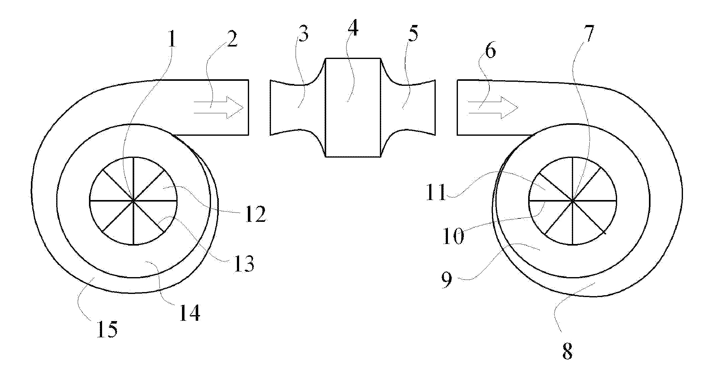
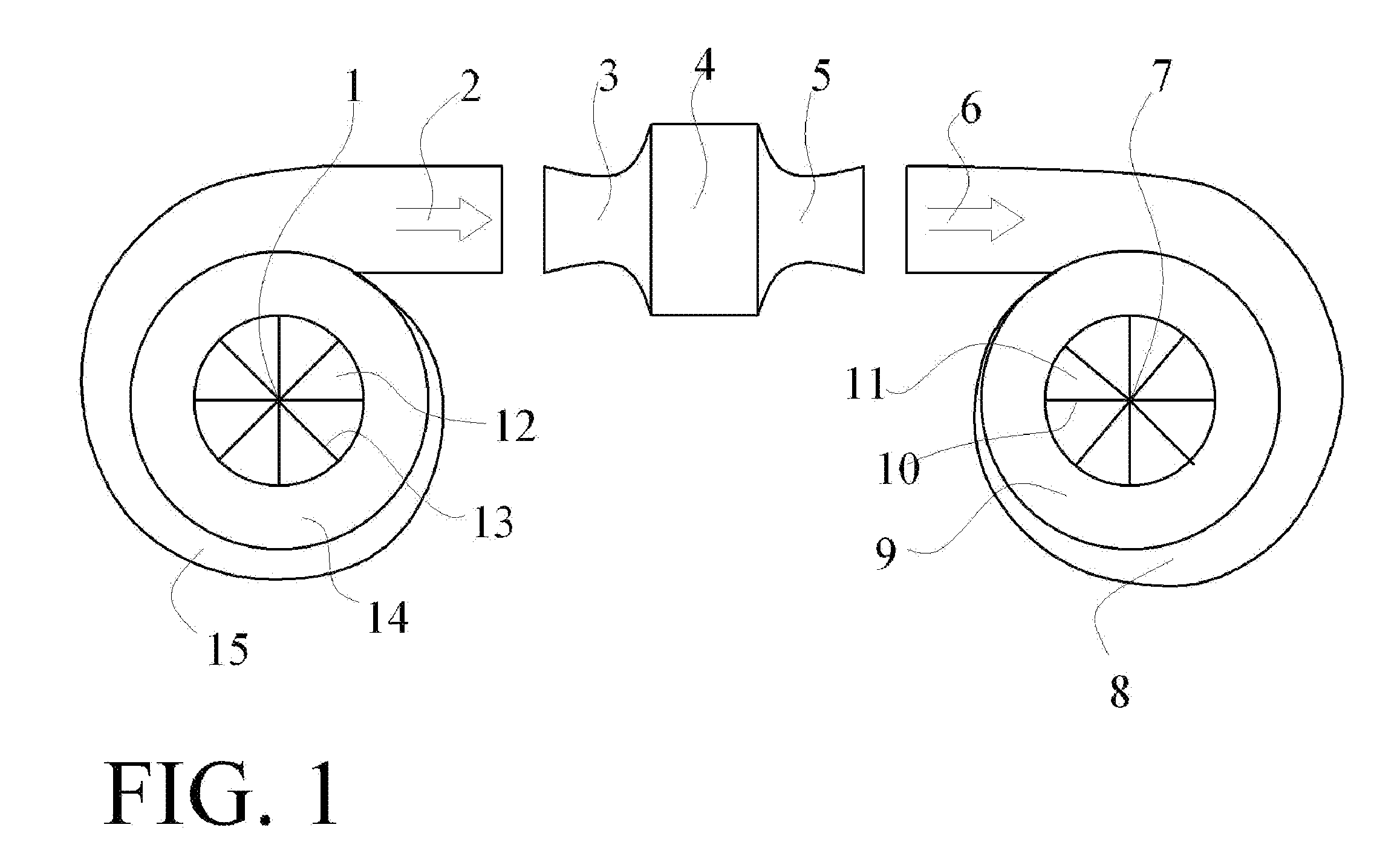
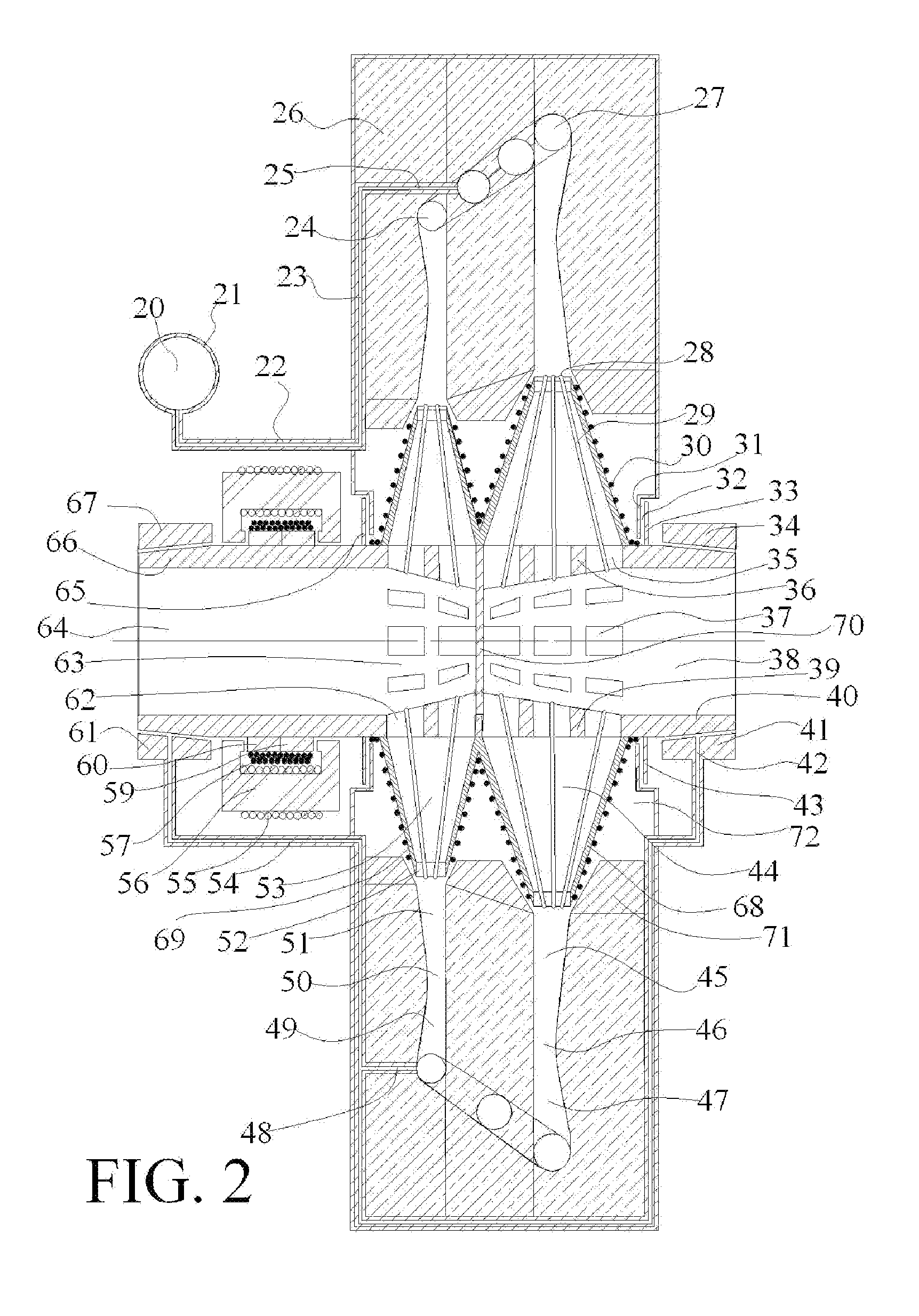
A ramjet engine (3, 4, 5), flying at Mach 3 has 64% efficiency, and at Mach 4 has 76% efficiency. Ramjet engines are currently only used for supersonic flight and have not been used as stationary engines with mechanical output. The present invention, in addition to subsonic flight, can be operated as a stationary engine, and can expand the use of the ramjet engine for mechanical output in vehicles, power plants, and in generator sets for large buildings, homes, and industry. The present invention provides the means to use ramjet engines as stationary engines by building nearly adiabatic compressors (1, 2, 12, 13, 14, 15) and expanders (6, 7, 8, 9, 10, 11) capable of (de-)compression ratios up to about 92:1 to supply the high energy gas/air required by ramjet engines, and shows how to replace de Laval nozzles with sonic converters (49, 50, 51) that convert supersonic to subsonic flow and sonic converters (45, 46, 47) that convert subsonic to supersonic flow without having choke areas.

Description

CROSS-REFERENCE TO RELATED APPLICATIONS[0001]This application relies on the disclosure and claims the benefit of the filing date of U.S. Provisional Application No. 61 / 039,406 filed Mar. 25, 2008, the disclosure of which is hereby incorporated by reference in its entirety.BACKGROUND OF THE INVENTION[0002]1. Field of the Invention[0003]This invention relates to the field of power plants. More particularly, the present invention relates to devices and methods used in the field of heat engines for various applications including mechanical drives. Embodiments of the present invention provide subsonic and stationary ramjet engines.[0004]2. Description of the Related Art[0005]To conserve fossil fuels and reduce the worldwide production of carbon dioxide, CO2, the most effective method is to increase the efficiency of automobile engines and other fuel burning engines. The efficiency of the average automobile engine on the road in the United States is approximately 21%. An automobile engine...

Claims


Application Information

Patent Timeline
IPC IPC(8): F02K7/10F02K1/38F01D5/18
CPCF01D1/32F02C3/165F02C7/08F05D2220/10F02K7/10Y02E20/14Y02T50/672F02K7/005Y02T50/60
Inventor CLAY, RUFUS G.HOCKADAY, ROBERT G.
Owner AMICABLE INVENTIONS LLC
Why Eureka
Try Eureka