
Mass air flow sensor adaptor

a mass air flow sensor and adaptor technology, applied in the field of internal combustion engines, can solve the problems of high cost of sensors, blockage or distortion of sensing ability of sensors, and increase the cost of sensors

Inactive Publication Date: 2009-10-01
CUMMINS INC
View PDF20 Cites 27 Cited by
  • Summary
  • Abstract
  • Description
  • Claims
  • Application Information

AI Technical Summary

Benefits of technology

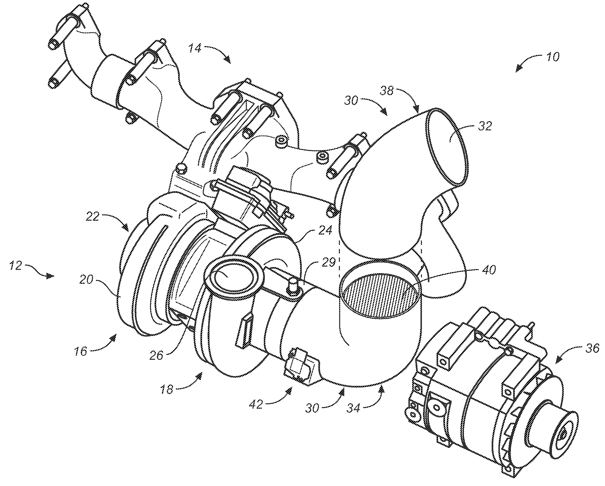
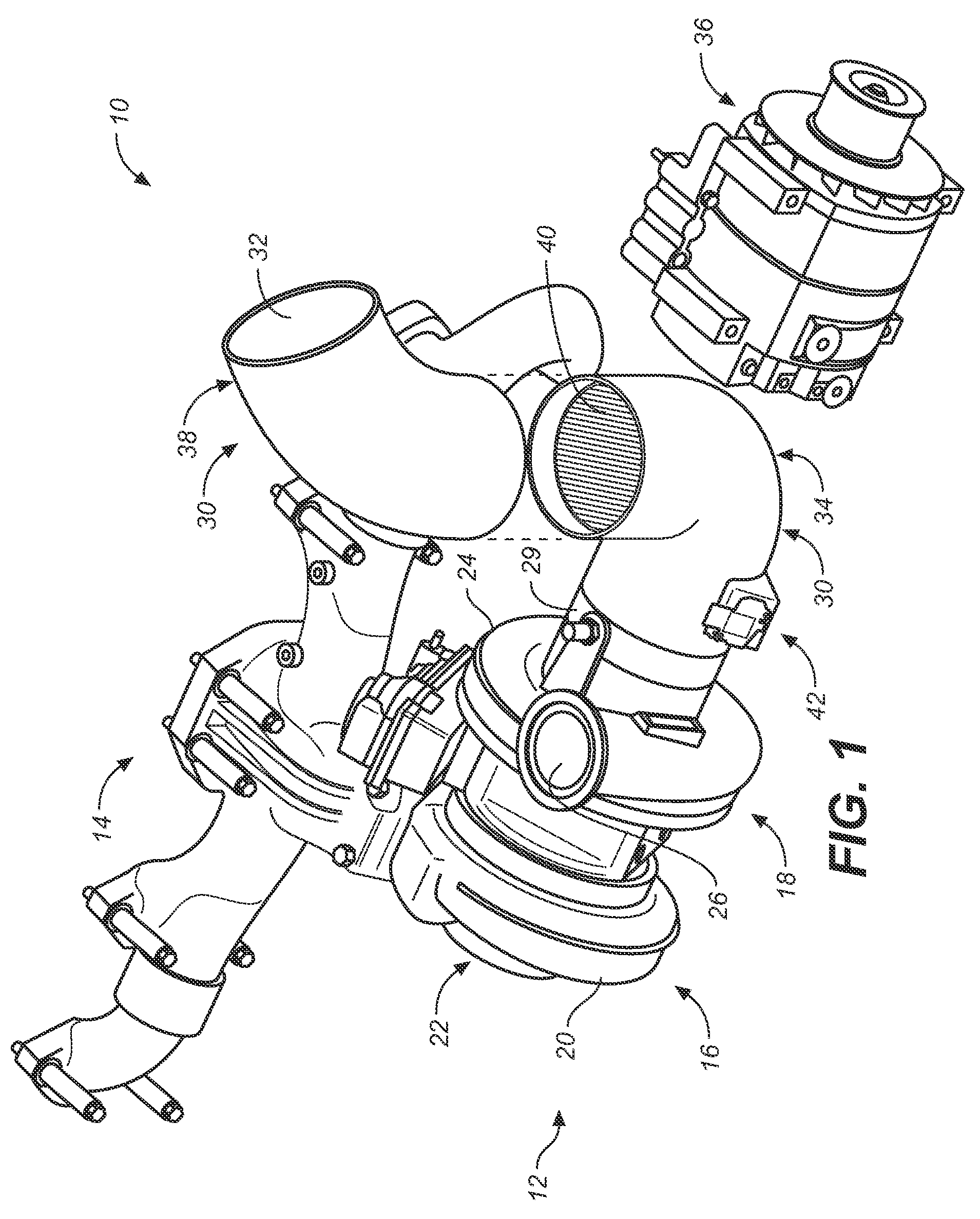
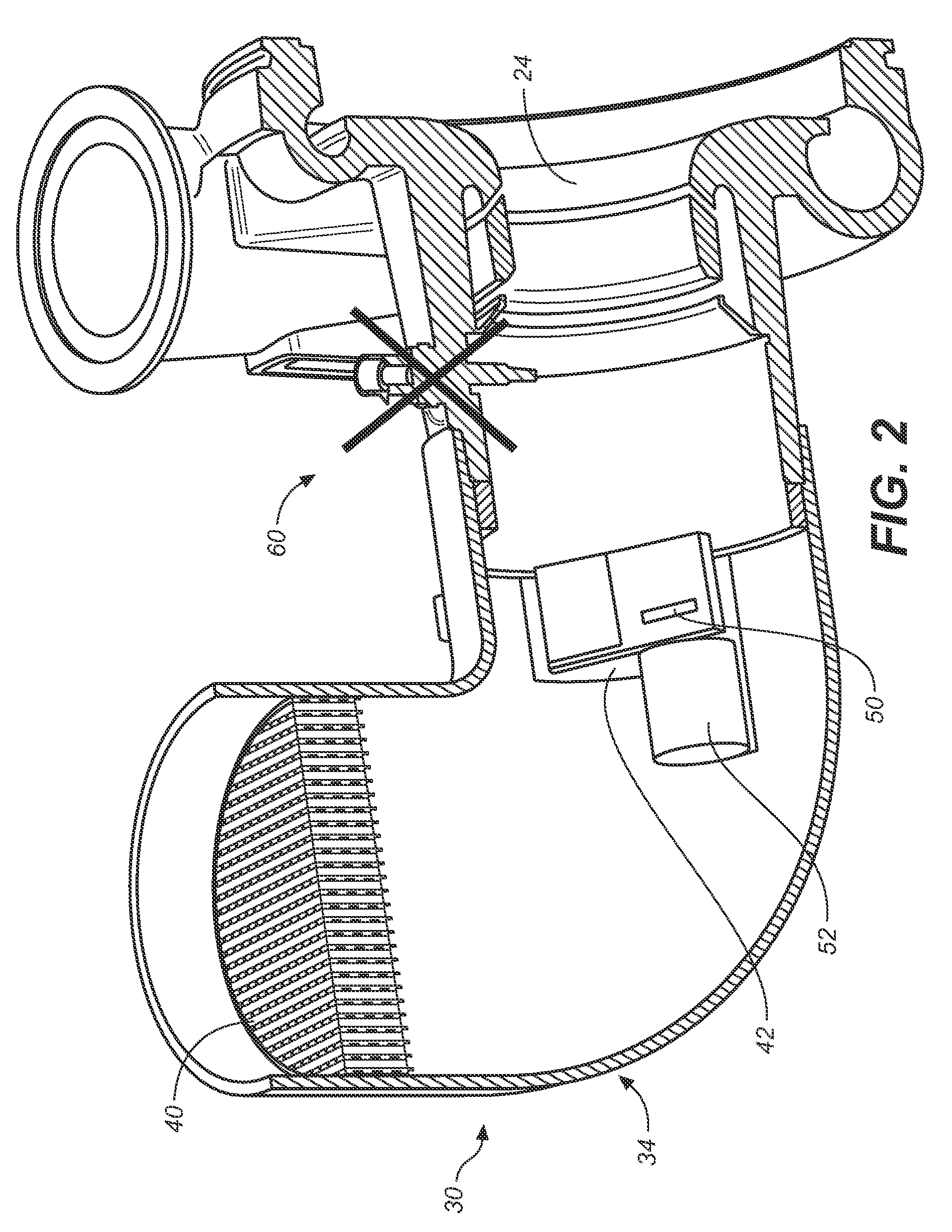
[0008]The present invention provides mass air flow sensing for an internal combustion engine, in which a low-cost mass air flow sensor can be provided for a single engine design or product that can be used in any of a variety of different vehicles and mechanisms, thus providing flexibility that accommodates variability in the air inlet and duct system connected to the engine.

Problems solved by technology

However, gas particulates build up and can block or distort the sensing ability of the sensors.
In addition, these types of sensors tend to be costly.
However, engines using MAF sensors are generally tailored for a specific vehicle and do not have the flexibility to accommodate different types of vehicles without affecting the consistency of MAF sensor output.
The air flow systems of different types of vehicles vary in their configuration and characteristics and can cause inconsistent MAF sensor performance depending on the air flow system characteristics.
Thus existing MAF sensor devices can only be incorporated into an engine when an engine manufacturer designs the entire vehicle, including the engine and air flow system.
This does not allow a single engine design with a MAF sensor to be manufactured and used with a variety of different types of vehicles.

Method used


Image

  • Mass air flow sensor adaptor
  • Mass air flow sensor adaptor
  • Mass air flow sensor adaptor

Examples


Embodiment Construction

[0013]The present invention relates to internal combustion engines, and more particularly to sensing mass air flow for internal combustion engines. The following description is presented to enable one of ordinary skill in the art to make and use the invention and is provided in the context of a patent application and its requirements. Various modifications to the preferred embodiment and the generic principles and features described herein will be readily apparent to those skilled in the art. Thus, the present invention is not intended to be limited to the embodiment shown but is to be accorded the widest scope consistent with the principles and features described herein.

[0014]The present invention is mainly described in terms of particular components provided in particular implementations. However, one of ordinary skill in the art will readily recognize that this apparatus will operate effectively in other implementations and applications. For example, the systems usable with the p...


PUM


Abstract

Mass air flow sensing for internal combustion engines. In one aspect, a sensor adaptor for use in an internal combustion engine includes an inlet housing including an approximately 90-degree elbow and directing air within the inlet housing to the internal combustion engine in an airflow direction. A mass air flow sensor is coupled to the housing at a location after the 90-degree elbow with respect to the airflow direction and senses the air flowing within the inlet housing.

Description

FIELD OF THE INVENTION[0001]The present invention relates to internal combustion engines, and more particularly to sensing mass air flow for internal combustion engines.BACKGROUND OF THE INVENTION[0002]Sensors are used in internal combustion engines to measure air flow and flow of other gases to allow greater control over engine operation. For example, measuring air flow allows calculation of desired characteristics such as air-fuel injection ratios in an electronically fuel-injected engine. The air flow information is provided to an engine control unit (ECU) to calculate and deliver the correct fuel mass to the engine. The air flow measurement can also allow an engine to measure gasses to meet emissions standards, such as when using exhaust gas recirculation (EGR), which recirculates a portion of exhaust gas back to the engine cylinders and limits the generation of nitrous oxide.[0003]Typically, air flow is measured using one or more sensors provided in appropriate locations in the...

Claims


Application Information

Patent Timeline
IPC IPC(8): G01F1/00F02M35/10
CPCF02M35/10144F02M35/10157F02M35/10222F02M35/10262F02M35/1038Y02T10/144G01F1/6842G01F15/00G01F15/185Y02T10/146F02M35/10386Y02T10/12
Inventor PERR, ANDREW P.CHAI, YONGQUAN
Owner CUMMINS INC
Learn More