Phase-cut dimming circuit

a phase-cut dimming circuit and phase-cut control technology, applied in process and machine control, ignition automatic control, instruments, etc., can solve the problems of permanently damage to load or other components, phase-cut dimming circuits cannot see directly the load,

Active Publication Date: 2009-10-01
POLARIS POWERLED TECH LLC
View PDF0 Cites 87 Cited by
  • Summary
  • Abstract
  • Description
  • Claims
  • Application Information

AI Technical Summary

Benefits of technology

[0006]Among other things, methods, systems, and devices are described for providing compatibility between phase-cut dimming circuitry and switched loads. Embodiments sense phase-cut dimming and convert the presence and amount of phase-cut dimming into analog and/or digital signals for use by power switching circuitry. The power switching circuitry may then use the signals to appropriately control their respective switched loads. Embodiments further provide preloading and startup control to maintain proper functioning of the circuitry in highly-dimmed conditions.
[0007]In one set of embodiments, a dimmer controller circuit arrangement is provided for use in a phase-cut dimming environment. The circuit arrangement includes a sensing module, configured to detect a conduction angle from a phase-cut voltage signal, the phase-cut voltage signal being generated by periodically cutting a periodic input voltage signal at the conduction angle; a logic processing module in operative communication with the sensing module and configured to generate a modulated output signal as a function of the conduction angle; and a load control signal generator module, in operative communication with the logic processing module and configured to generate a load control signal as a function of the modulated output signal. In some embodiments, the circuit arrangement further includes a housing configured to house at least a portion of the sensing module, the logic processing module, and the load control signal generator module.
[0008]In another set of embodiments, a circuit arrangement is provided for use in a phase-cut dimming environment. The circuit arrangement includes a phase-cut dimming module, configured to receive a periodic input voltage signal and cut the input voltage signal at a conduction angle to generate a phase-cut signal; a rectifier module, configured to rectify the phase-cut voltage signal to generate a bus voltage signal; and a dimmer controller module, operable to convert the phase-cut voltage signal to a load control signal as a function of the conduction angle. The dimmer controller module includes a sensing module, configured to detect the conduction angle from the phase-cut voltage signal; a logic processing module in operative communication with the sensing module and configured to generate a modulated output signal as a function of the conduction angle; and a load control signal generator module, in operative communication with the logic processing module and configured to generate a load control signal as a function of the modulated output signal.
[0009]Some embodiments further include a preload module, having a switched current generator configured to generate a cur...

Problems solved by technology

The switching power circuitry may cause the phase-cut dimming circuit to be unable directly to see the load.
The indirect connection betwee...

Method used


Image

  • Phase-cut dimming circuit
  • Phase-cut dimming circuit
  • Phase-cut dimming circuit

Examples


Embodiment Construction

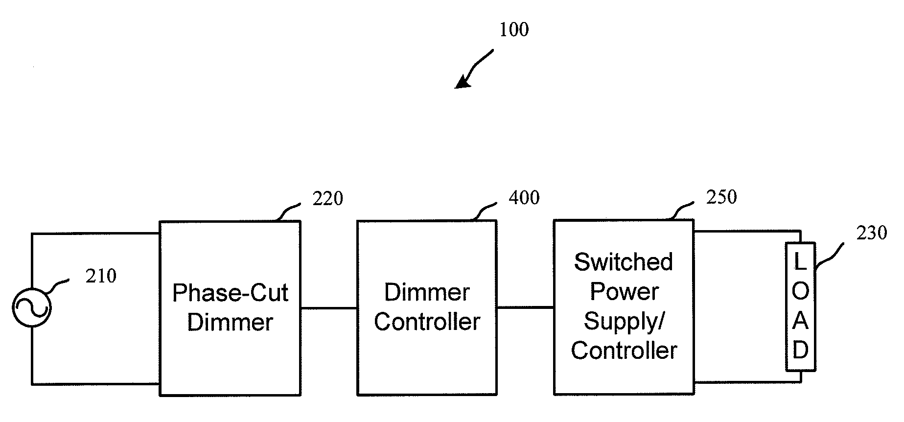
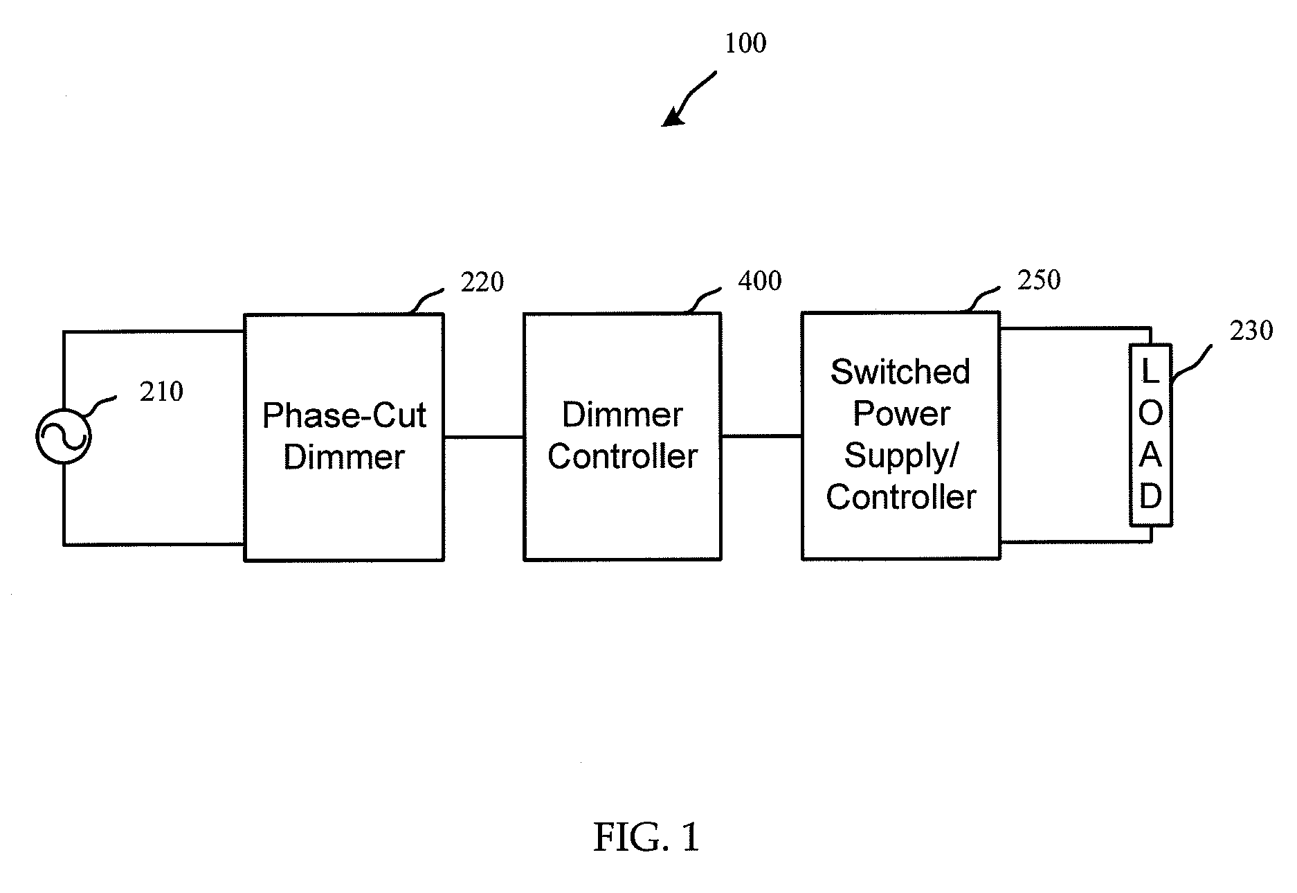
[0026]Many typical dimmer circuits used in commercial and residential applications include phase-cut dimmer circuits. The phase-cut dimmer receives a sinusoidal input voltage (e.g., typically mains line voltage), and “cuts” the waveform at some phase angle set by the dimmer control. This effectively switches the power being delivered to a connected load, thereby reducing the average power being seen by the load. Where the load is directly connected to the dimmer circuit, the reduced average power may directly result in a reduced load output (e.g., reduced brightness of a light bulb). However, where the load is switched (e.g., indirectly connected to the dimmer circuit), the switching circuitry may typically be incompatible with the dimming circuitry. For example, certain compact fluorescent bulbs, and other loads connected to switched power supplies or controllers may not work with typical phase-cut dimmers.

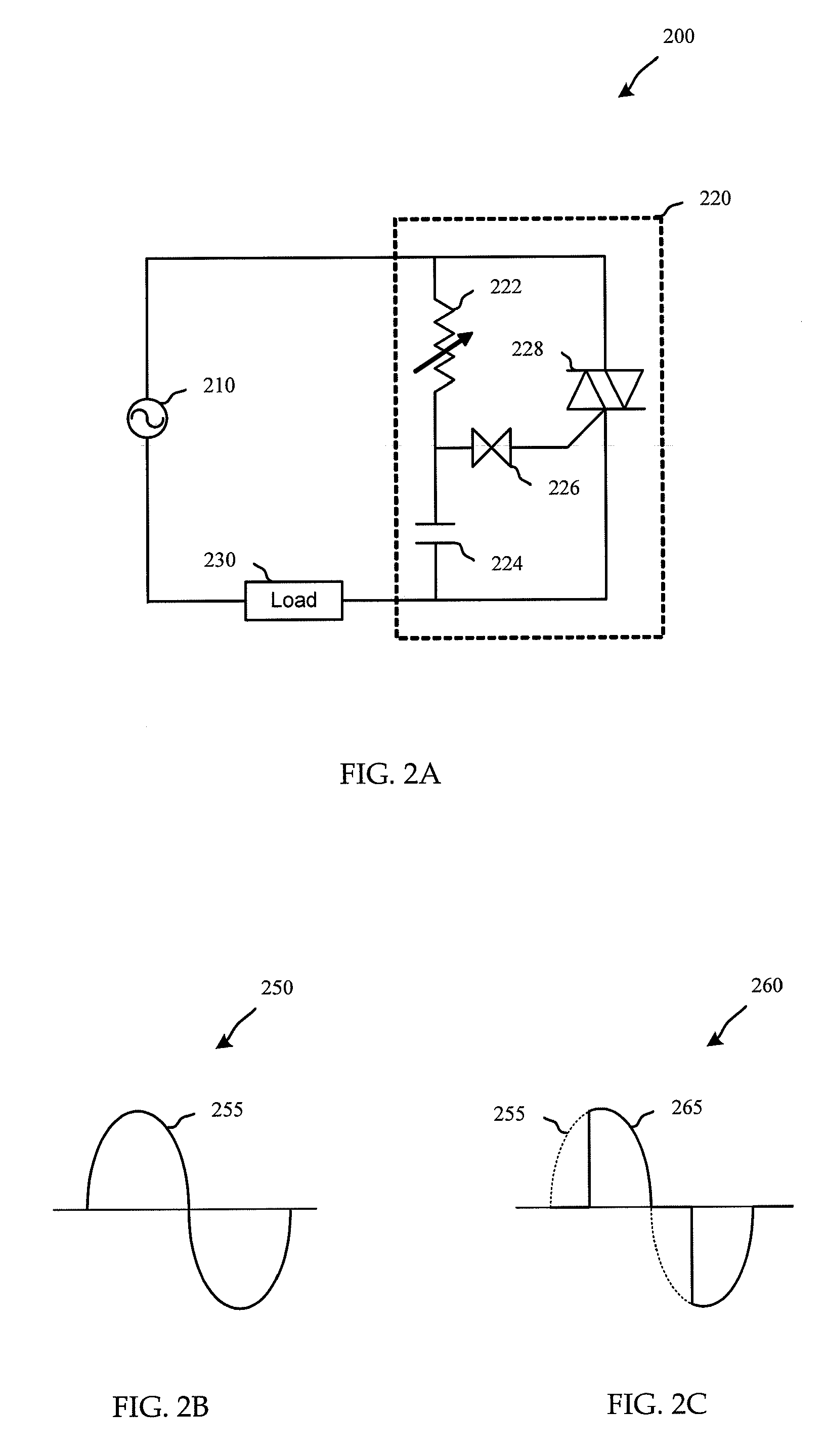
[0027]Phase-cut dimming circuits are typically based on circuit elements, li...


PUM

PropertyMeasurementUnit
Electric potential / voltageaaaaaaaaaa
Angleaaaaaaaaaa
Currentaaaaaaaaaa

Abstract

Methods, systems, and devices are described for sensing a phase-cut dimming signal and outputting a control signal compatible with a switching power circuit. Embodiments of the invention generate at least one of a low-frequency pulse-wave-modulated control signal, an analog output control signal, or a digital (e.g., higher-frequency pulse-wave-modulated) output control signal. Some embodiments further provide preloading and/or startup control functionality to allow proper functioning of the circuitry under small-conduction-angle (i.e., highly dimmed) conditions.

Description

CROSS-REFERENCES[0001]This application claims priority from co-pending U.S. Provisional Patent Application No. 61 / 039,339, filed Mar. 25, 2008, entitled “PHASE-CUT DIMMING CIRCUIT” (Attorney Docket No. 027342-000300US), which is hereby incorporated by reference, as if set forth in full in this document, for all purposes.BACKGROUND[0002]The present invention relates to integrated circuits in general and, in particular, to phase-cut control circuits.[0003]Phase-cut dimmer circuits are common circuits used in many commercial and residential applications for dimming and power control. For example, phase-cut dimmers are used to control light or heat output, motor speed, etc. They may be typically located inside standard wall receptacles (e.g., to interface with standard wall switches and outlets), or integrated with line cords or controlled equipment (e.g., a variable speed drill).[0004]It is generally desirable to connect a phase-cut dimming circuit directly to the load it intends to co...

Claims


Application Information

Patent Timeline
IPC IPC(8): H02J3/12
CPCH05B39/08H05B39/02
Inventor IRISSOU, PIERRECOLMET-DAAGE, ETIENNEDREXLER, BERNARD
Owner POLARIS POWERLED TECH LLC
Why Eureka
Try Eureka