

Multilayer transformer component
a transformer and multi-layer technology, applied in the direction of basic electric elements, coils, electrical equipment, etc., can solve the problems of increasing characteristic variation and the risk of output signal characteristics varying depending
- Summary
- Abstract
- Description
- Claims
- Application Information
AI Technical Summary
Benefits of technology
Problems solved by technology
Method used
Image


Examples
Embodiment Construction
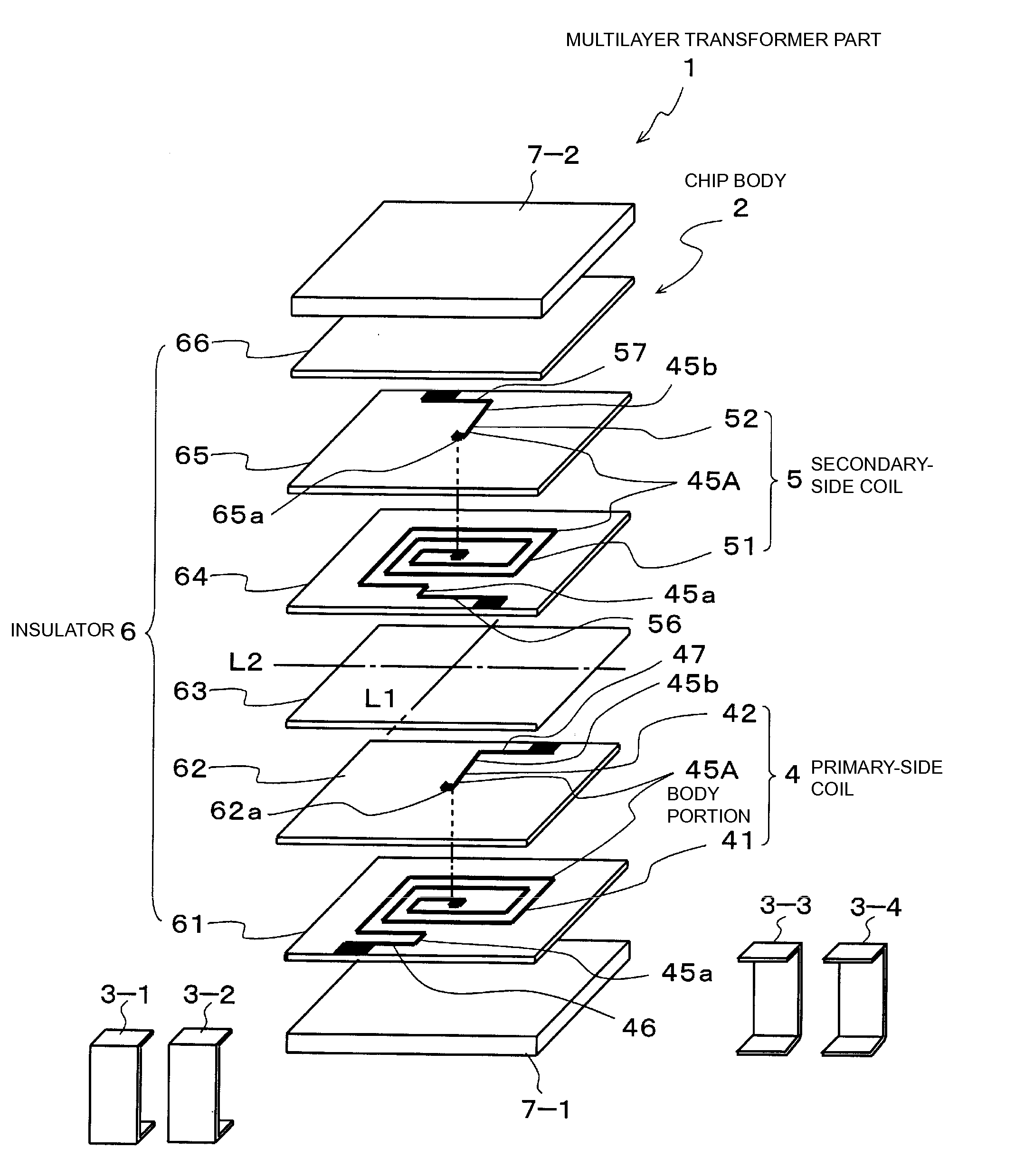
[0041]Preferred embodiments of the present invention will be described below with reference to the drawings.
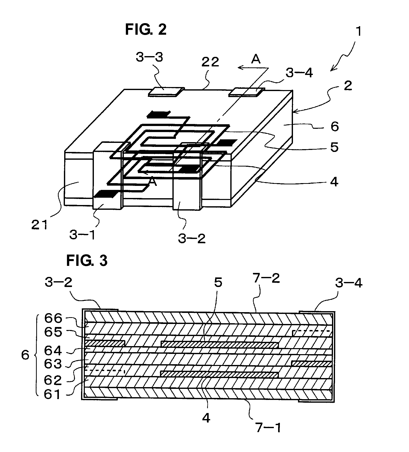
[0042]FIG. 1 is an exploded perspective view illustrating a multilayer transformer component according to a preferred embodiment of the present invention. FIG. 2 is a perspective view of the multilayer transformer component, the view illustrating a primary-side coil and a secondary-side coil in a see-through view. FIG. 3 is a sectional view taken along a line A-A in FIG. 2.
[0043]As illustrated in FIGS. 1 and 2, a multilayer transformer component 1 includes a chip body 2 and first to fourth external electrodes 3-1 to 3-4.
[0044]The chip body 2 includes a primary-side coil 4 and a secondary-side coil 5 that are layered within an insulator 6.
[0045]As illustrated in FIGS. 1 and 3, the insulator 6 is defined by insulating layers 61 to 66. The primary-side coil 4 and the secondary-side coil 5 are provided in predetermined ones of the insulating layers 61 to 66 by patterning, and the ...
PUM
| Property | Measurement | Unit |
|---|---|---|
| shape | aaaaa | aaaaa |
| sizes | aaaaa | aaaaa |
| density | aaaaa | aaaaa |
Abstract
Description
Claims
Application Information