LED luminaire

a technology of led luminaires and diodes, which is applied in the direction of fixed installation, lighting and heating apparatus, lighting support devices, etc., can solve the problems of unsafe high currents, high energy consumption, and high energy consumption of luminaires, and achieve low energy consumption, low maintenance, and low heat generation

Active Publication Date: 2009-10-01
MCGEHEE MICHAEL EUGENE +1
View PDF8 Cites 25 Cited by
  • Summary
  • Abstract
  • Description
  • Claims
  • Application Information

AI Technical Summary

Benefits of technology

[0036]According to the first exemplary embodiment of the present invention, a lighting module disposed on the base includes a mounting plate and a plurality of light emitting diodes provided on the mounting plate. The light emitting diodes (LEDs) provides a light source having a low energy requirement, a maintained voltage and current, low heat generation, low maintenance, shock and vibration resistance, a long life span, good color rendering, little delay in producing illumination, and no harmful elements.
[0037]According to the second exemplary embodiment of the present invention, a top pla

Problems solved by technology

However, there are a number of drawbacks to using HPS devices in luminaires.
This creates unsafe high currents which could prove deadly to human and animal life in certain situations.
In addition, the HPS device generally requires more energy as it draws nearer to the end of its life span.
In turn, the burning of the gas creates a tremendous amount of heat.
Again, the amount of heat created by the HPS device could be hazardous to both humans and animals.
The HPS device also contains mercury, which is known to be hazardous to humans and animals as well as the environment.
Further, the HPS device has a high maintenance requirement.
The life span of the bulb may be further negatively affected by various shock and vibration.
In addition, the HPS device has very poor color rendering and

Method used


Image

  • LED luminaire
  • LED luminaire
  • LED luminaire

Examples


Embodiment Construction

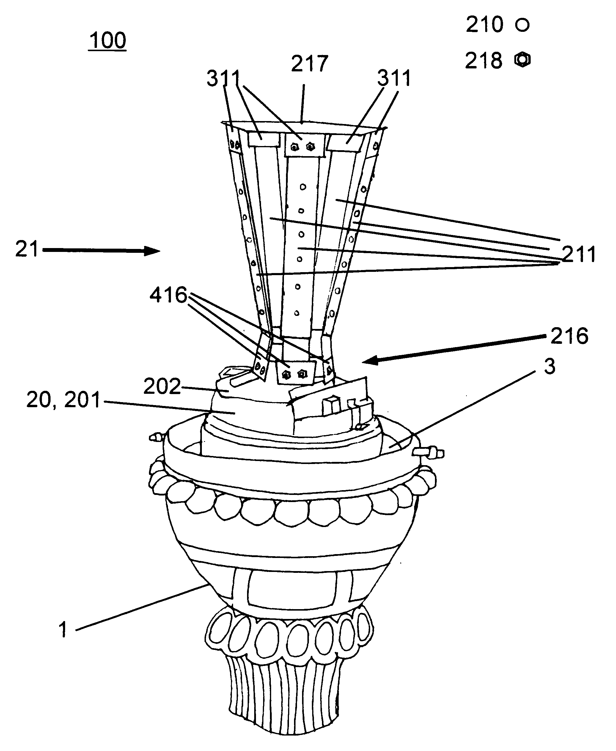
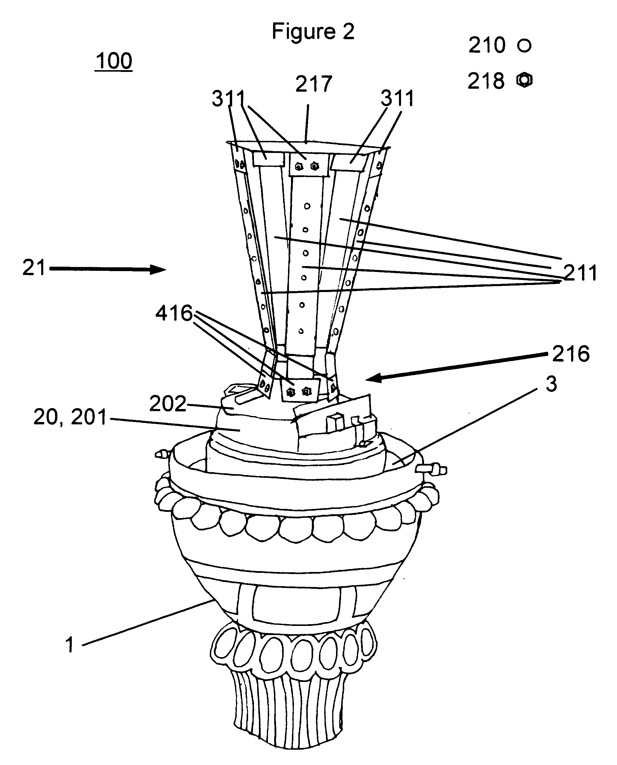
[0051]Referring now to the drawings, and more particularly to FIGS. 1-12, there are shown exemplary embodiments of the structures and method according to the present invention. For simplicity of description, all embodiments of the present invention are exemplarily applied to illumination of outdoor and public environments. One of ordinary skill in the art would clearly realize that the present invention is not limited to these applications. On the contrary, the present invention is advantageously applicable to all applications requiring illumination. Examples of applicable environments include household lamp and fixture lighting, artistic and performance lighting, emergency lighting, traffic signal lighting, and so on.

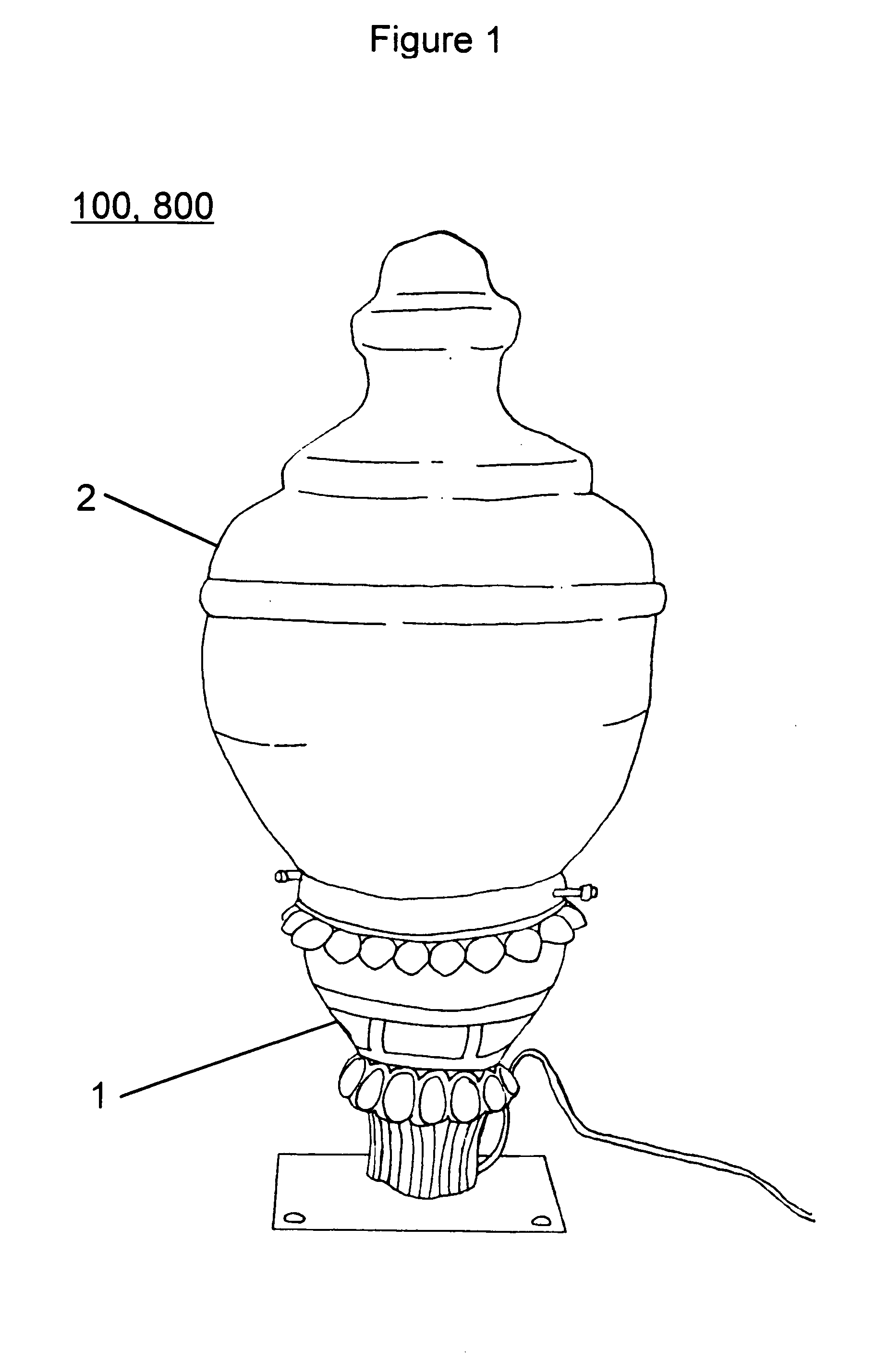
[0052]FIG. 1 illustrates an exemplary outer portion of luminaires 100, 800 of the first and second exemplary embodiments of the present invention. The luminaires 100, 800 includes a base 1 and a cover 2. The cover 2 provided for the luminaires 100, 800 is universal in ...


PUM


Abstract

A luminaire includes a base, a lighting module disposed on the base, the lighting module including a mounting plate, and a plurality of light emitting diodes provided on the mounting plate, and a cover surrounding the lighting module and secured in the base, the cover optimally directing light emitted by the plurality of light emitting diodes.

Description

CROSS-REFERENCE TO RELATED APPLICATIONS[0001]This application claims the benefit of U.S. Provisional Application No. 61 / 072,073, filed Mar. 27, 2008.BACKGROUND OF THE INVENTION[0002]1. Field of the Invention[0003]The present invention generally relates to the use of light emitting diodes (LEDs) in lighting applications, and, more specifically, to the use of LEDs to illuminate outdoor and public environments with light fixtures having a decorative and pleasant appearance.[0004]2. Description of the Related Art[0005]In certain outdoor and public environments, especially those environments in which lack of lighting is an issue, it is necessary to provide illumination for public safety and liability purposes. While the need for this illumination is geared primarily toward public safety and proactive preventative measures, it is generally desired that the provided illumination be implemented in an attractive and pleasing manner that will enhance the decorative ambiance of the particular ...

Claims


Application Information

Patent Timeline
IPC IPC(8): F21V21/00H01J9/24
CPCF21K9/00F21S8/088F21Y2111/007F21W2131/10F21Y2101/02F21V29/004F21Y2115/10F21Y2107/40F21V29/70F21V15/01
Inventor MCGEHEE, MICHAEL EUGENEADINOLFI, JOHN THOMAS
Owner MCGEHEE MICHAEL EUGENE
Why Eureka
Try Eureka