LED Lamp Having Higher Efficiency

Inactive Publication Date: 2009-10-01
CHYN WEN LONG
View PDF3 Cites 70 Cited by
  • Summary
  • Abstract
  • Description
  • Claims
  • Application Information

AI Technical Summary

Benefits of technology

[0011]A further objective of the present invention is to provide an LED lamp, wherein the heatsink plate has a surface provided with a plurality of ventilating holes connected to the receiving space of the heatsink housing to enhance a heat convection effect between the heatsink plate and the heats

Problems solved by technology

However, the LED is a heat source and easily produces a high temperature during operation, so that it is necessary to provide a heat sink to carry away the heat produced by the LED so as to achieve a heat dissipation effect.
However, the conventional heat

Method used


Image

  • LED Lamp Having Higher Efficiency
  • LED Lamp Having Higher Efficiency
  • LED Lamp Having Higher Efficiency

Examples


Embodiment Construction

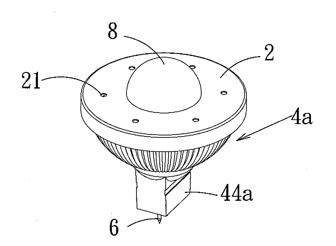
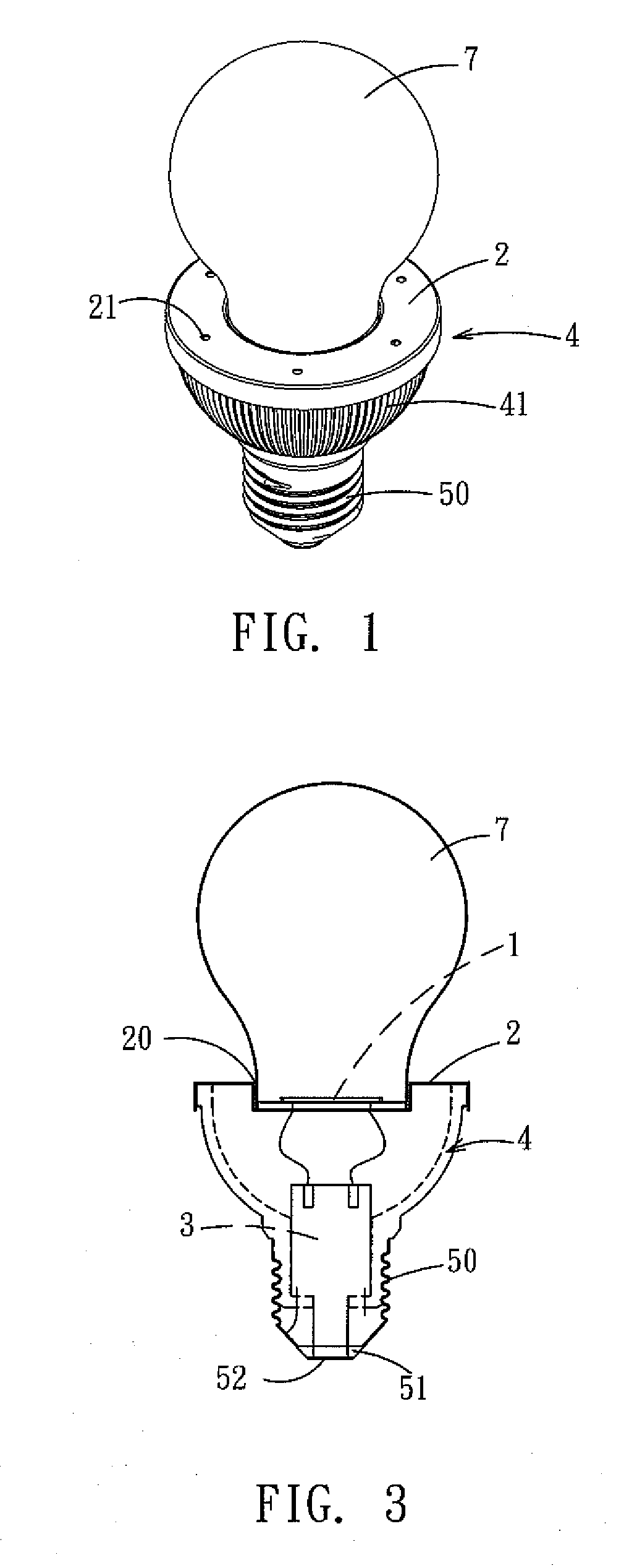
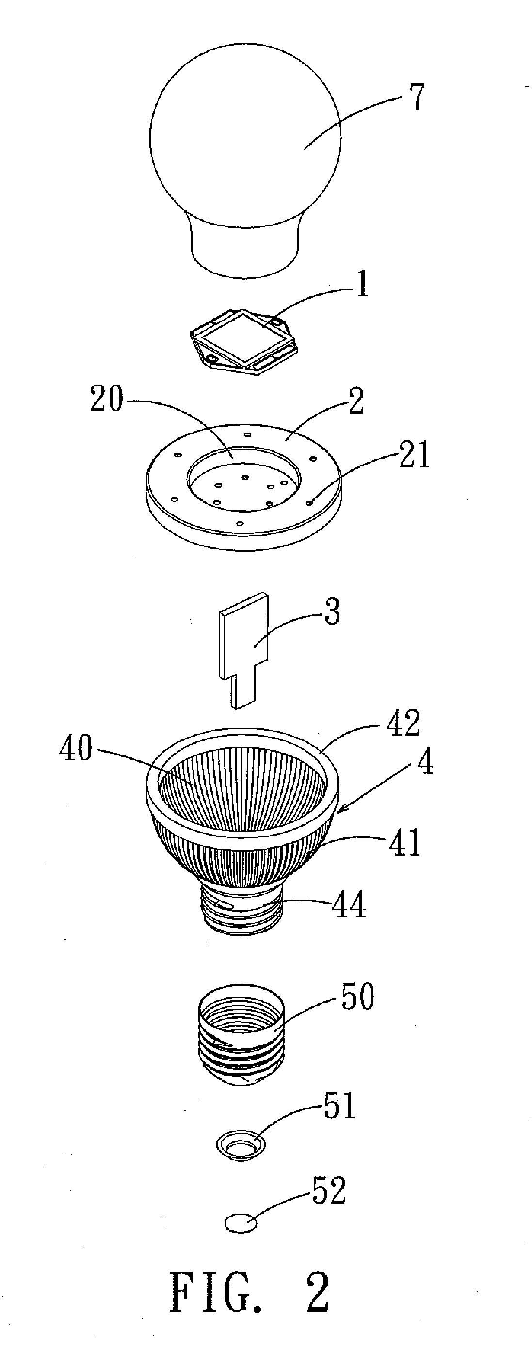
[0020]Referring to the drawings and initially to FIGS. 1-3, an LED (light emitting diode) lamp in accordance with the preferred embodiment of the present invention comprises a heatsink housing 4, a heatsink plate 2 mounted on the heatsink housing 4, an LED module 1 mounted on the heatsink plate 2, and a circuit board 3 mounted in the heatsink housing 4 and electrically connected to the LED module 1 to electrically connect the LED module 1 to an external power supply (not shown). The LED lamp further comprises a lamp shade 7 mounted on the heatsink plate 2 to encompass the LED module 1.

[0021]The heatsink housing 4 forms a porous structure with a greater heat dissipation feature. The porous structure formed by the heatsink housing 4 has a high specific surface area and is made of a nonmetallic powder (formed by an injection molding process) having greater heat conductivity, such as Al2O3, Zr2O, AlN, SiN, BN, WC, C, SiC, crystalline SiC, Recrystalline SiC (ReSiC) and the like.

[0022]The...


PUM


Abstract

An LED lamp includes a heatsink housing, a heatsink plate mounted on the heatsink housing, an LED module mounted on the heatsink plate, and a circuit board mounted in the heatsink housing and electrically connected to the LED module. Thus, when the LED module is operated, the heat produced by the LED module is transferred by a heat conduction of the heatsink plate and by a heat convection between the heatsink plate and the heatsink housing, so that the heat produced by the LED module is carried away exactly and quickly, thereby enhancing the heat dissipation effect of the LED module.

Description

BACKGROUND OF THE INVENTION[0001]1. Field of the Invention[0002]The present invention relates to a lamp and, more particularly, to an LED (light emitting diode) lamp to provide a lighting function.[0003]2. Description of the Related Art[0004]A conventional LED lamp comprises an LED (light emitting diode) to provide a lighting function. However, the LED is a heat source and easily produces a high temperature during operation, so that it is necessary to provide a heat sink to carry away the heat produced by the LED so as to achieve a heat dissipation effect. A conventional heat sink generally comprises a heatsink element, such as a metallic heatsink fin, a heat conductive tube, a chill enabling chip, a heat dissipation board, a cooling fan and the like, so as to achieve a heat dissipation effect. However, the conventional heat sink cannot dissipate the heat from the heat source exactly and quickly, thereby greatly decreasing the heat dissipation efficiency. In addition, the convention...

Claims


Application Information

Patent Timeline
IPC IPC(8): F21V29/00
CPCF21V29/004F21Y2101/02F21K9/135F21V29/85Y10S362/80F21V29/773F21V23/006F21K9/232F21Y2115/10F21K9/238F21V29/89
Inventor CHYN, WEN-LONG
Owner CHYN WEN LONG
Why Eureka
Try Eureka