Wind guiding cover
A technology of air guide cover and air duct, which is applied in the field of air guide cover, which can solve the problems of limited heat dissipation speed and dangerous working state of heating elements 15, and achieve the effects of increasing space, strengthening heat convection effect, and reducing wind resistance
- Summary
- Abstract
- Description
- Claims
- Application Information
AI Technical Summary
Problems solved by technology
Method used
Image

Examples
no. 1 example
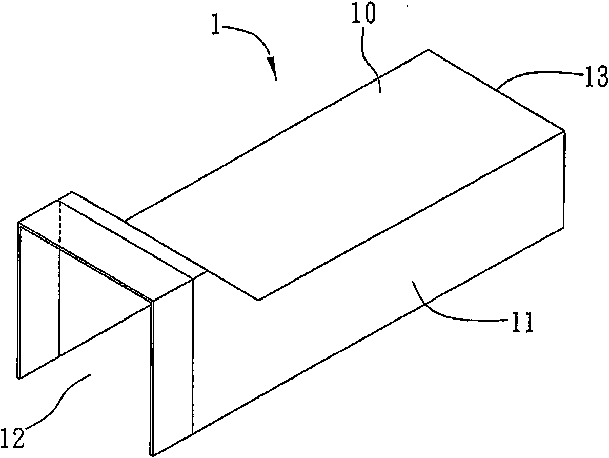
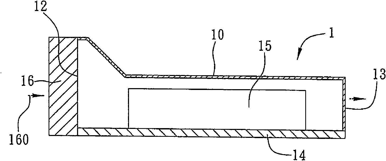
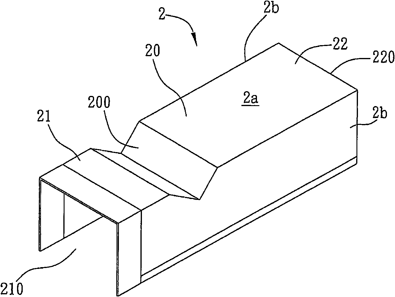
[0045] see Figure 2A and Figure 2B , is a schematic diagram of an embodiment of the wind guide cover of the present invention. The structure of the windshield shown in this embodiment and other embodiments is only illustrative, as long as it is applied to an electronic device with a heating element, including the heat exchange area, the opposite air inlet part and the air outlet part, in this The heat exchange area is provided with an air flow turbulence part, so that the air flow passes through the air flow turbulence part to form a disturbance, all of which are applicable to the present invention.
[0046] Such as Figure 2A As shown, in this embodiment, the air guide cover 2 is a bottomless cover body composed of a top cover 2a and two side walls 2b extending downward along two opposite sides of the top cover 2a, and each of the side walls 2b can be It is integrally formed on the top cover 2a.
[0047] The wind guide cover 2 includes: a heat exchange area 20, a relati...
no. 2 example
[0055] see image 3 The difference between this embodiment and the first embodiment lies in the structure of the heat exchange area 20, and the design of the other related air guide covers 2 is substantially the same, therefore, the same elements and corresponding descriptions will be omitted, and will not be repeated, hereby stated.
[0056] As shown in the figure, when the air flow turbulence part 200' of the heat exchange area 20 has two V-shaped folded edge structures, the degree of turbulent flow formed by the cold air flow 50 is increased to increase the heat dissipation effect (described later); and it can be Make the lengths and inclination angles of the two first inclined surfaces 200a, 200a' different or the same, and / or the lengths and inclination angles of the two second inclined surfaces 200b, 200b' be different or the same; of course, in other embodiments , the concave fold length, slope angle, and concave fold depth of each of the V-shaped hem structures can be...
no. 3 example
[0059] see Figure 4 The difference between the present embodiment and the second embodiment lies in the structure of the air inlet portion 21', and the design of the other related wind guide covers 2 is substantially the same, therefore, the same elements and corresponding descriptions will be omitted, and will not be described again. It is hereby stated.
[0060] As shown in the figure, when the height of the fan module 5 is relatively high relative to the heat source, the height of the air inlet 210 of the air guide cover 2 is also relatively high. The pressure part 211 is provided between the air inlet 210 and the heat exchange area 20, so that the cold air flow 50 generated by the fan module 5 is pressed down and concentrated on the heat exchange area 20, so that the flow velocity of the cold air flow 50 is increased; In the embodiment, the airflow depressing part 211 is a downward inclined surface and is connected to the first inclined surface 200a of the airflow turbul...
PUM
 Abstract
Description
Claims
Application Information