X-ray radiographic apparatus and method

a radiographic apparatus and x-ray technology, applied in the direction of radiation beam directing means, instruments, applications, etc., can solve problems such as diagnosis obstacles, and achieve the effect of good accuracy and long length

Inactive Publication Date: 2009-10-01
FUJIFILM CORP
View PDF5 Cites 36 Cited by
  • Summary
  • Abstract
  • Description
  • Claims
  • Application Information

AI Technical Summary

Benefits of technology

[0013]The present invention has been made in view of the aforementioned circumstances, and an object of the present invention is to provide an X-ray radiographic apparatus and method that enables easily performing long length imaging in which an alignment marker is unfailingly positioned in an overlapping area of an X-ray plat panel detector regardless of the long-length imaging area and / or the X-ray source position.
[0015]In other words, since the position in which an alignment marker provided on a screen is projected on the X-ray flat panel detector varies depending on the long length imaging area and / or the X-ray source position, and the entire area of these varying positions of the marker is set to be a fixed overlapping area. Then, when determining a plurality of field-of-view areas for dividing an imaging area for long length imaging into a plurality of areas and taking images, the respective field-of-view areas are determined so that the fixed overlapping areas for adjacent field-of-view areas overlap each other, and meanwhile, the position to which the X-ray flat plane detector is moved is determined for each of the determined field-of-view areas so that an X-ray is applied to the field-of-view area. As a result of controlling the X-ray generation unit so that an X-ray is applied only to each of the field-of-view areas determined as described above and controlling the position to which the X-ray flat panel detector is moved, the marker can unfailingly be projected on an overlapping area (fixed overlapping area) of the X-ray flat panel detector regardless of the long length imaging area and / or the X-ray source position. Also, when connecting adjacent X-ray images, the images are connected so that the markers shown in the fixed overlapping areas are aligned with each other, enabling provision of a long-length image in which the images are connected with good accuracy.
[0017]A third aspect of the present invention provides the X-ray radiographic apparatus according to the first or second aspect, wherein: a plurality of the markers are provided in the screen at an interval smaller than a length in the vertical direction of the X-ray flat panel detector; and the fixed overlapping area setting device sets the fixed overlapping area for each of the markers. This enables long length imaging in which three or more images are connected, and also enables taking an of any long-length region of a subject such as the entire backbone or the entire legs.
[0023]According to the present invention, regardless of the conditions for long length imaging (long length imaging area, the X-ray source height and the object distance), long length imaging can automatically be performed so that an alignment marker is unfailingly positioned in an overlapping area of an X-ray flat panel detector, enabling provision of a long length of image in which images are connected with good accuracy using markers shown in the overlapping areas of the respective adjacent images.

Problems solved by technology

In this case, however, a problem may arise in the markers may be obstacles for diagnosis.

Method used


Image

  • X-ray radiographic apparatus and method
  • X-ray radiographic apparatus and method
  • X-ray radiographic apparatus and method

Examples


Embodiment Construction

[0036]Hereinafter, preferred embodiments of an X-ray radiographic apparatus and method according to the present invention will be described with reference to the accompanying drawings.

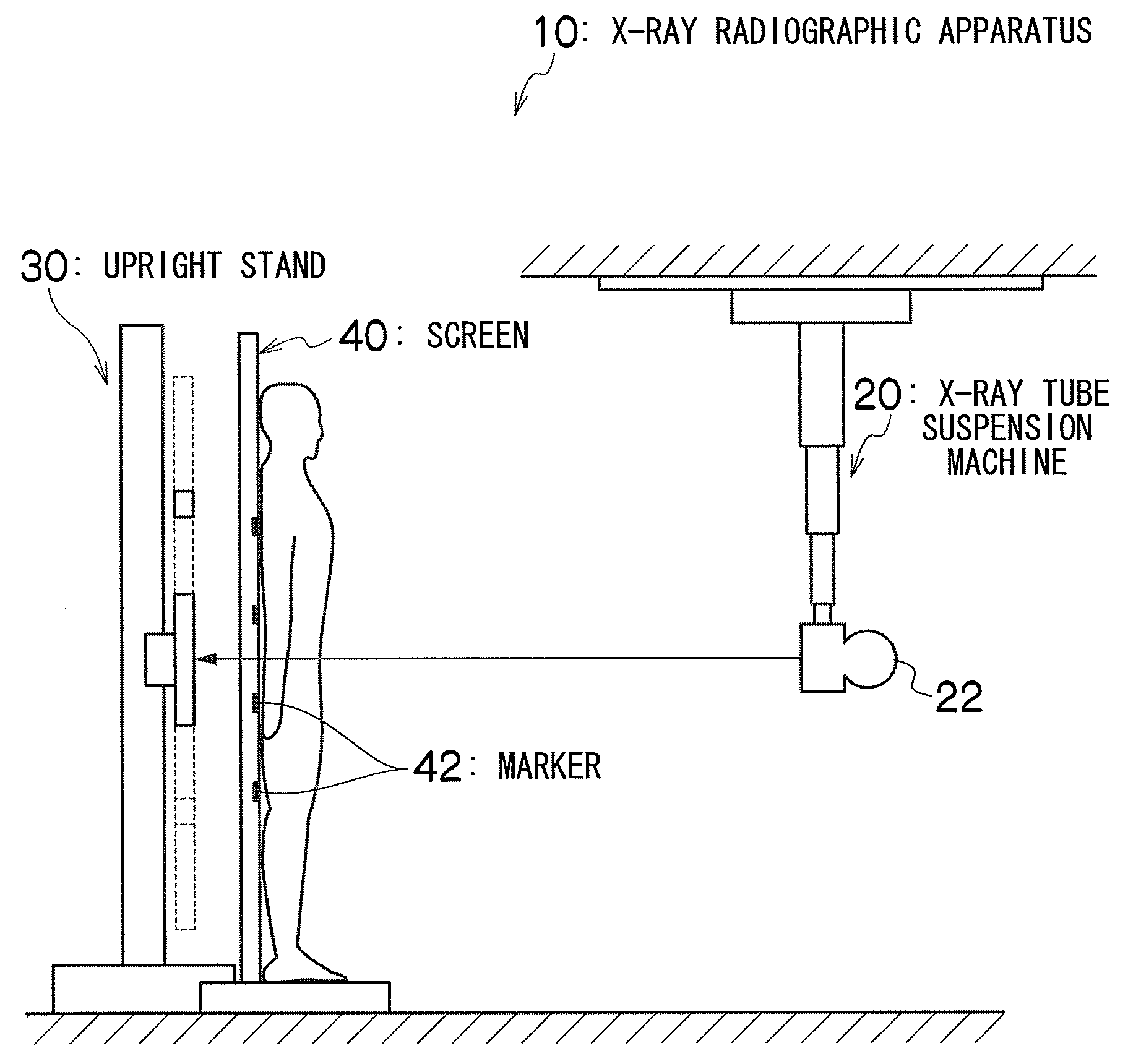
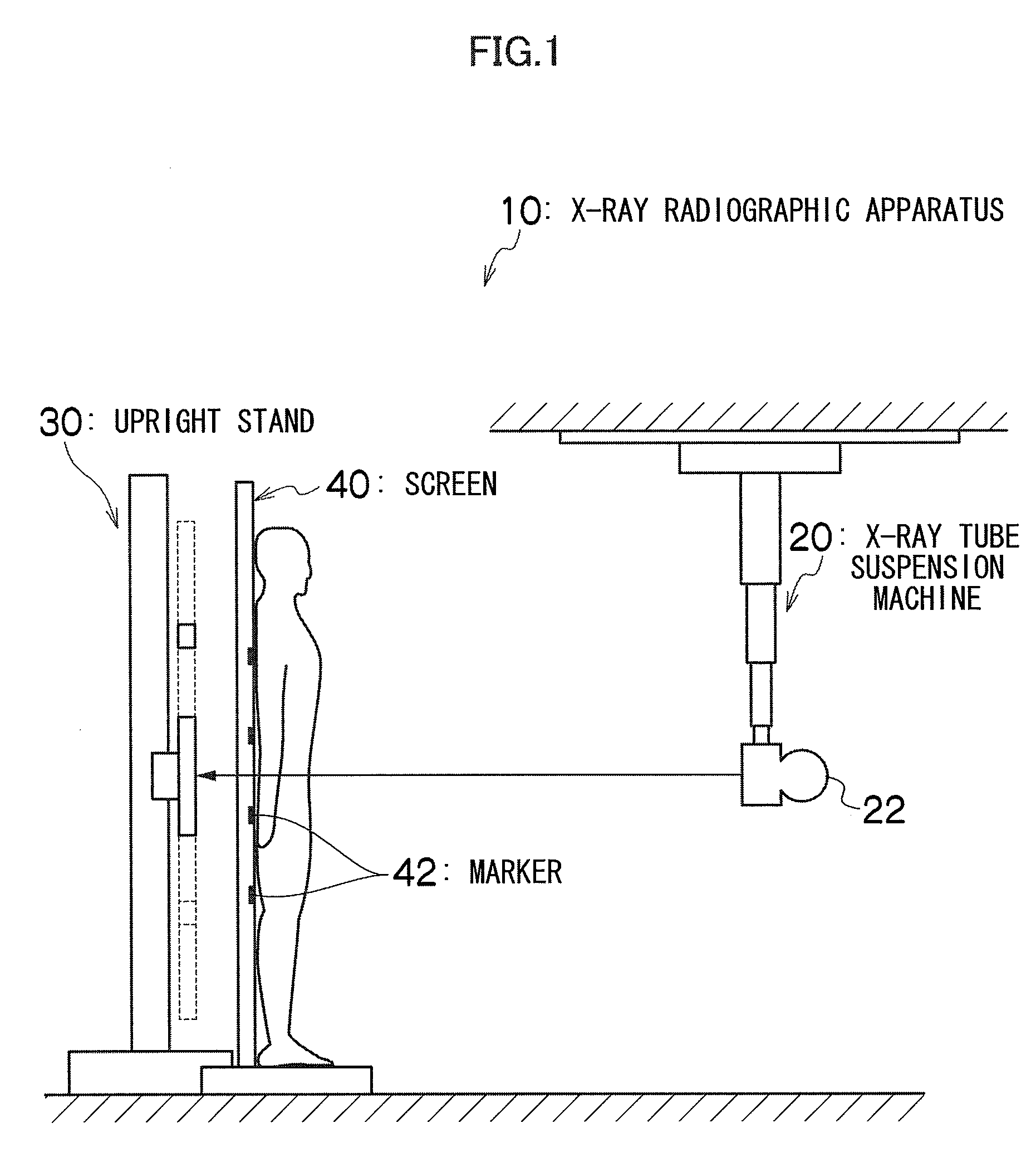
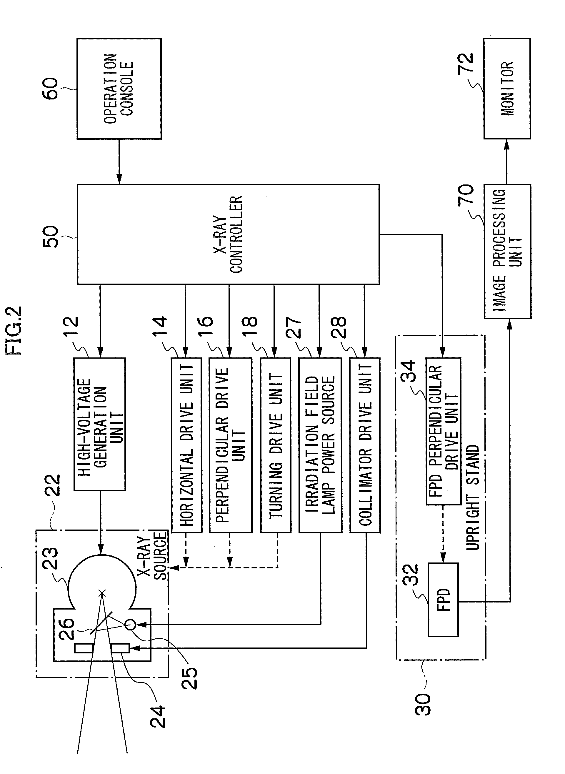
[0037]FIG. 1 is a schematic overview of the appearance of an X-ray radiographic apparatus according to the present invention, and FIG. 2 is a block diagram of an embodiment of an X-ray radiographic apparatus.

[0038]As illustrated in FIGS. 1 and 2, this X-ray radiographic apparatus 10 mainly includes an X-ray tube suspension machine 20, an upright stand 30, a screen 40, an X-ray controller 50, an operation console 60 and an image processing unit 70.

[0039]The X-ray tube suspension machine 20 supports an X-ray source 22, and moves this X-ray source 22 in a horizontal direction by means of an overhead travelling-type horizontal drive unit 14, and also moves the X-ray source 22 in a perpendicular (vertical) direction by means of a perpendicular drive unit 16. Also, the X-ray source 22 is configured so that i...


PUM

PropertyMeasurementUnit
field of viewaaaaaaaaaa
lengthaaaaaaaaaa
incident angleaaaaaaaaaa

Abstract

An entire area of an FPD on which an alignment marker provided in a screen is projected is set in advance as a fixed overlapping area (Ctop to Cbottom) according to the long length imaging area and / or the X-ray source position. When determining a plurality of field-of-view area areas for dividing an imaging area for long length imaging into a plurality of areas and taking images, the field-of-view areas (FOVNT to FOVNB) and the FPD positions PN corresponding to the respective field-of-view areas are determined so that adjacent field-of-view areas overlap each other at the set fixed overlapping area. The X-ray source height, the X-ray irradiation direction, the collimator aperture angle and the FPD position are controlled so as to apply an X-ray only to each of the determined field-of-view areas.

Description

BACKGROUND OF THE INVENTION[0001]1. Field of the Invention[0002]The present invention relates to an X-ray radiographic apparatus and method, and specifically relates to a technique for obtaining one long length of X-ray image by taking plural X-ray images and connecting these X-ray images.[0003]2. Description of the Related Art[0004]In plain X-ray radiography, a long length of image is sometime taken for a region with a long length, such as the entire backbone or the entire legs.[0005]Conventional computed radiography (CR) is X-ray radiography using a storage phosphor sheet (imaging plate: IP) instead of an X-ray film. In the CR, when taking a long length of image, images are taken with IPs overlapped each other, and a long length of image is obtained by combining images read from the respective IPs (Japanese Patent Application Laid-Open No. 2000-232976). Also, in this case, more accurate alignment can be performed by providing markers made of, e.g., lead, in the region where the IP...

Claims


Application Information

Patent Timeline
Patent Type & Authority Applications(United States)
IPC IPC(8): G01N23/04A61B6/08
CPCA61B6/5241A61B6/4441
Inventor YAMAGUCHI, YOSHITAKA
Owner FUJIFILM CORP
Why Eureka
Try Eureka