

Image encoding device
a technology of encoding device and image, which is applied in the direction of code conversion, instruments, computing, etc., can solve the problems of deteriorating encoding efficiency, improper encoding, and deteriorating decoding image quality, and achieve the effect of improving encoding efficiency
- Summary
- Abstract
- Description
- Claims
- Application Information
AI Technical Summary
Benefits of technology
Problems solved by technology
Method used
Image

Examples
embodiment 1
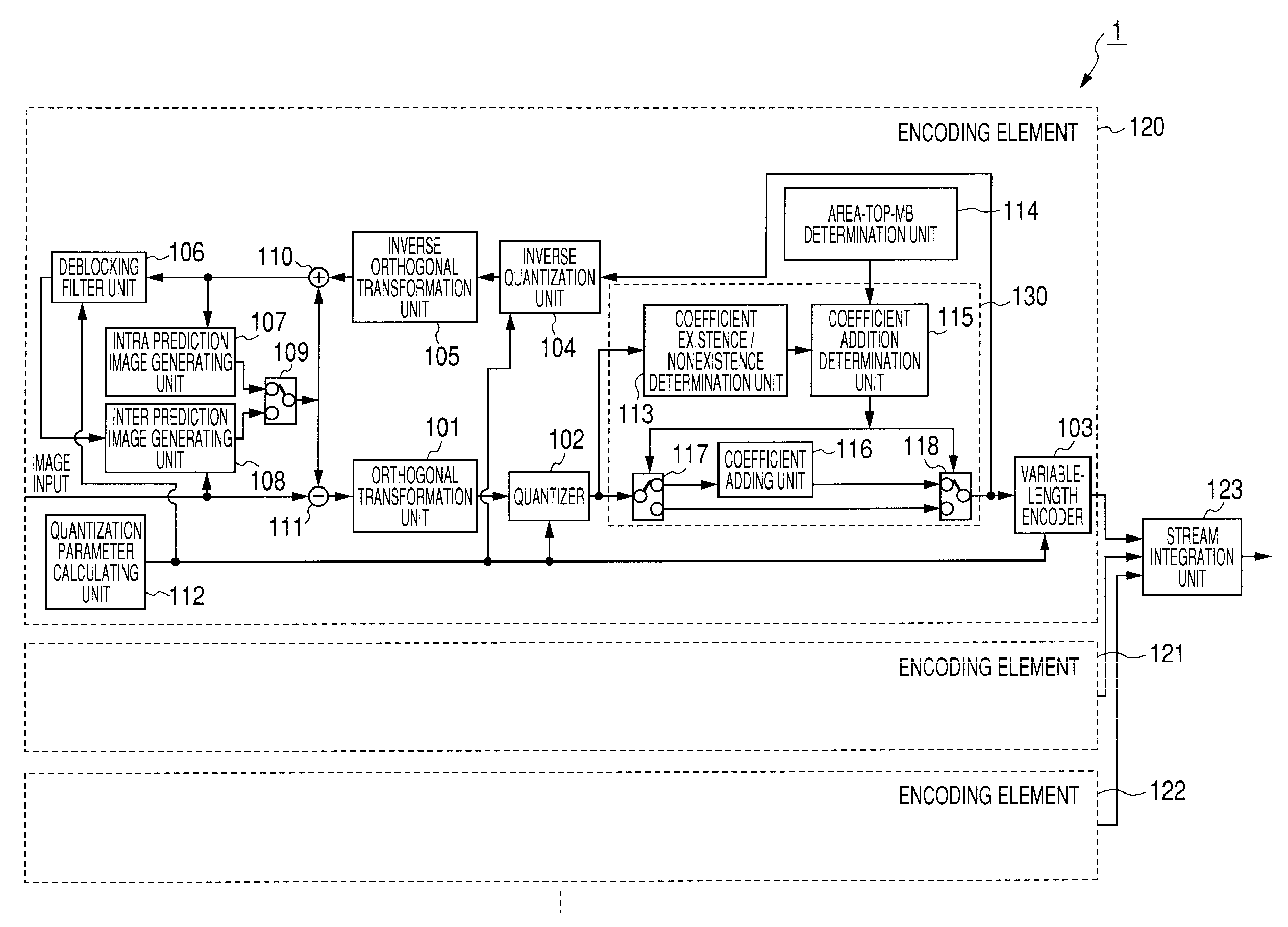
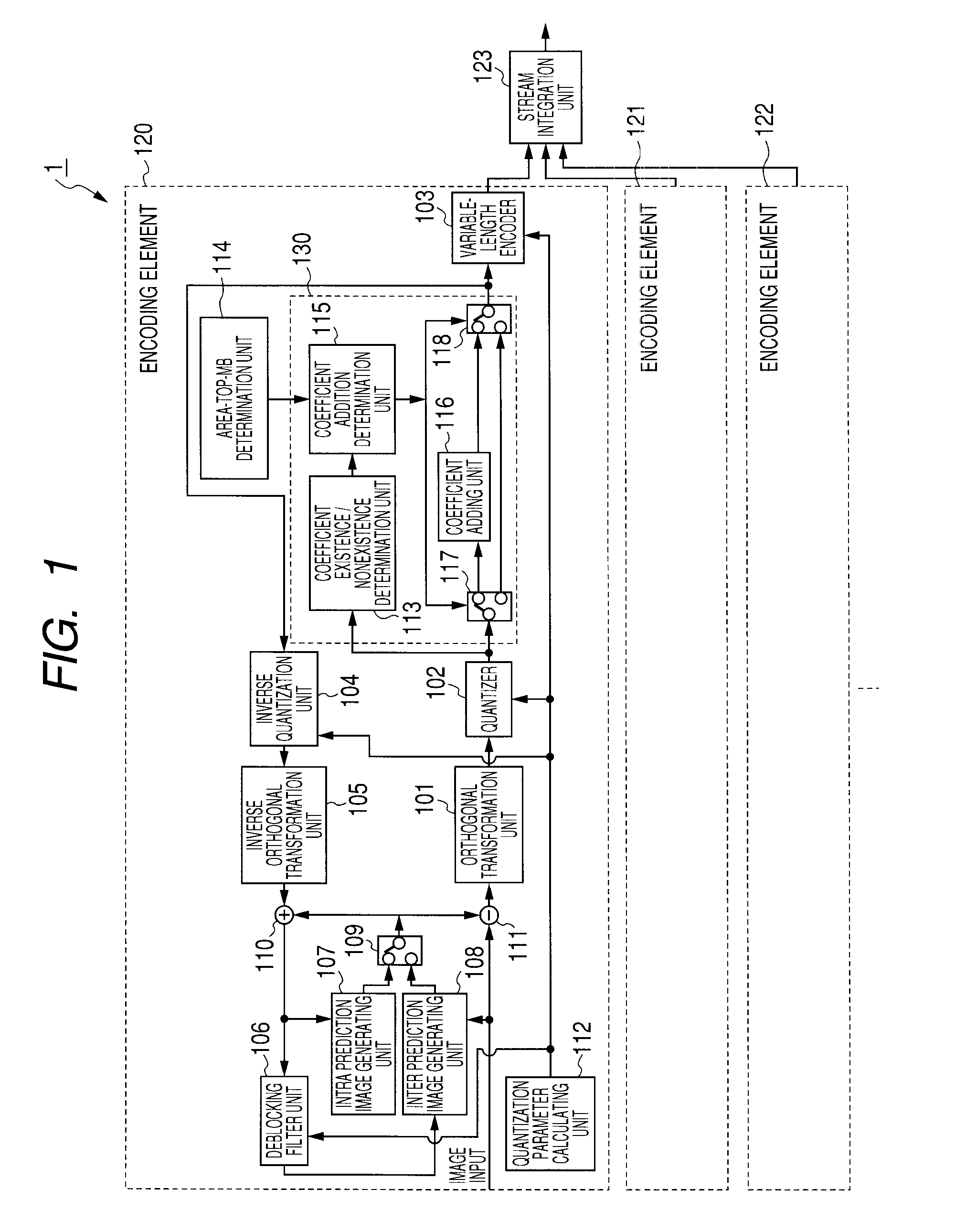
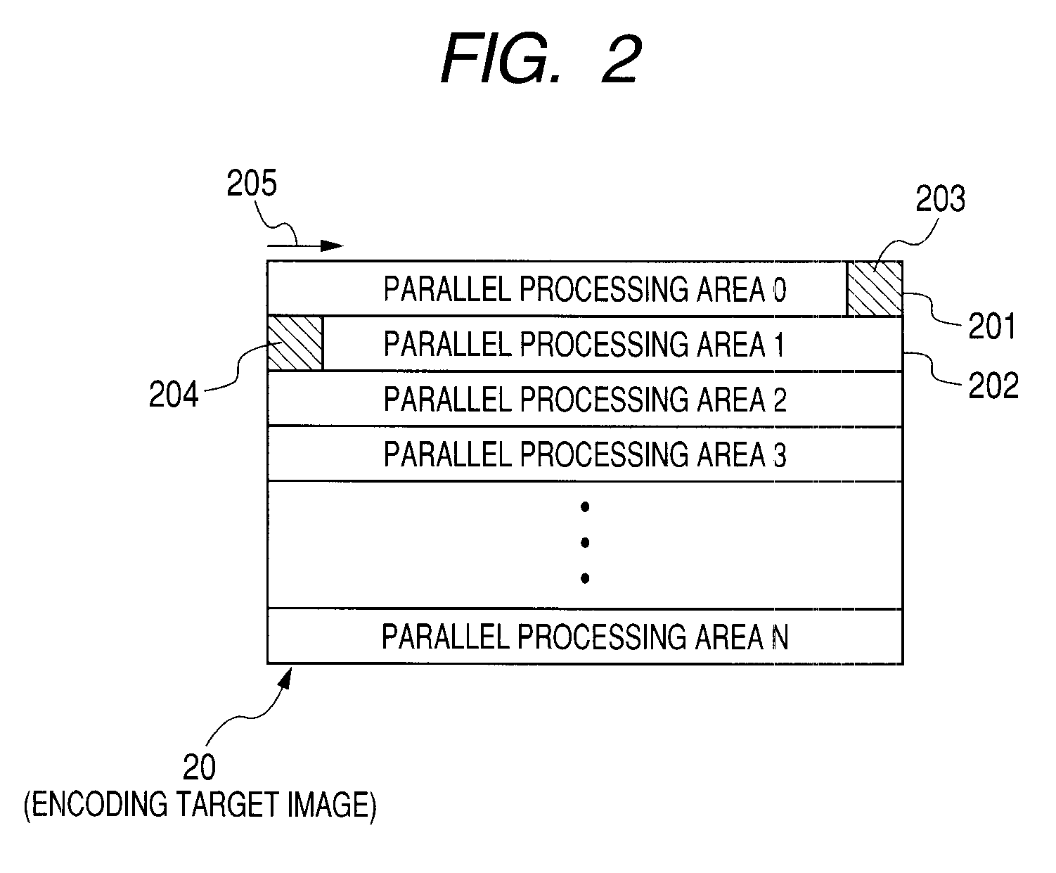
[0046]FIG. 1 illustrates configuration of an image encoding device according to an embodiment of the present invention. An image encoding device 1 illustrated in FIG. 1 encodes a macroblock of an encoding target image by parallel processing sequentially from the top of a parallel processing area, in conformity with H.264 and possesses encoding elements 120-122 provided for every parallel processing area. For example, when an area 20 in FIG. 2 is assumed to be an encoding target image, one rectangle typically illustrated by rectangles 203, 204 stands for a macroblock. A macroblock is a set of 16×16 pixels. The area of one line of macroblocks in the encoding target image 20 is a parallel processing area as illustrated by a rectangle 202. In FIG. 2, it is seen that the encoding target image 20 is comprised of from a parallel processing area 0 to a parallel processing area N. The image encoding device 1 performs encoding in parallel, in the direction of an arrow 205, from the macroblock...
embodiment 2
[0054]FIG. 3 illustrates configuration of an image encoding device according to another embodiment of the present invention. The configuration of FIG. 1 employs the coefficient compensation unit 130 in order to suppress the generating of a skip macroblock in the processing of a top macroblock of a parallel processing area. On the contrary, an image encoding device 2 of FIG. 3 suppresses the generating of a skip macroblock by the processing of a variable-length encoder 233.
[0055]FIG. 3 is different from FIG. 1 in the point that a variable-length encoder 233 and an area-top MB determination unit 235 are employed, in place of the coefficient compensation unit 130 and the variable-length encoder 103 of FIG. 1. The area-top MB determination unit 235 possesses the same function as the area-top MB determination unit 114 of FIG. 1. The other circuit blocks possessing the same function as in FIG. 1 are attached with the same reference symbols as in FIG. 1, and the detailed explanation thereo...
embodiment 3
[0059]FIG. 5 illustrates configuration of an image encoding device according to further another embodiment of the present invention. An image encoding device 3 of FIG. 5 employs the configuration in which, by using a coefficient compensation unit similar to FIG. 1, an equal quantization parameter is assigned to a top macroblock and a last macroblock which sandwich a parallel processing area boundary, and the generation of a skip macroblock in the last macroblock lying across the parallel processing area boundary is suppressed. Difference with FIG. 1 is as follows. In each of encoding elements 320-322, an area-top-MB / last-MB determination unit 344 is employed in place of the area-top MB determination unit 114, a quantization parameter controlling unit 350 common to all the encoding elements 320-322 is provided, and a coefficient compensation unit 330 similar to the coefficient compensation unit 130 is provided.
[0060]The area-top-MB / last-MB determination unit 344 determines whether a ...
PUM
 Abstract
Description
Claims
Application Information