
Lost frame compensating method, audio encoding apparatus and audio decoding apparatus

a decoding apparatus and audio encoding technology, applied in the field of frame erasure concealment method, speech encoding apparatus, speech decoding apparatus, can solve the problems of decoding speech signal marked distortion, inability to conceal the immediate preceding frame information, etc., and achieve the effect of suppressing the degradation of the quality of the current frame decoding signal

Inactive Publication Date: 2009-10-01
PANASONIC CORP
View PDF23 Cites 49 Cited by
  • Summary
  • Abstract
  • Description
  • Claims
  • Application Information

AI Technical Summary

Benefits of technology

[0011]According to the present invention, when a speech codec that utilizes past excitation information of an adaptive codebook or the like is used as a main encoder, degradation in the quality of a decoded signal of the current frame can be suppressed even if a preceding frame is lost.

Problems solved by technology

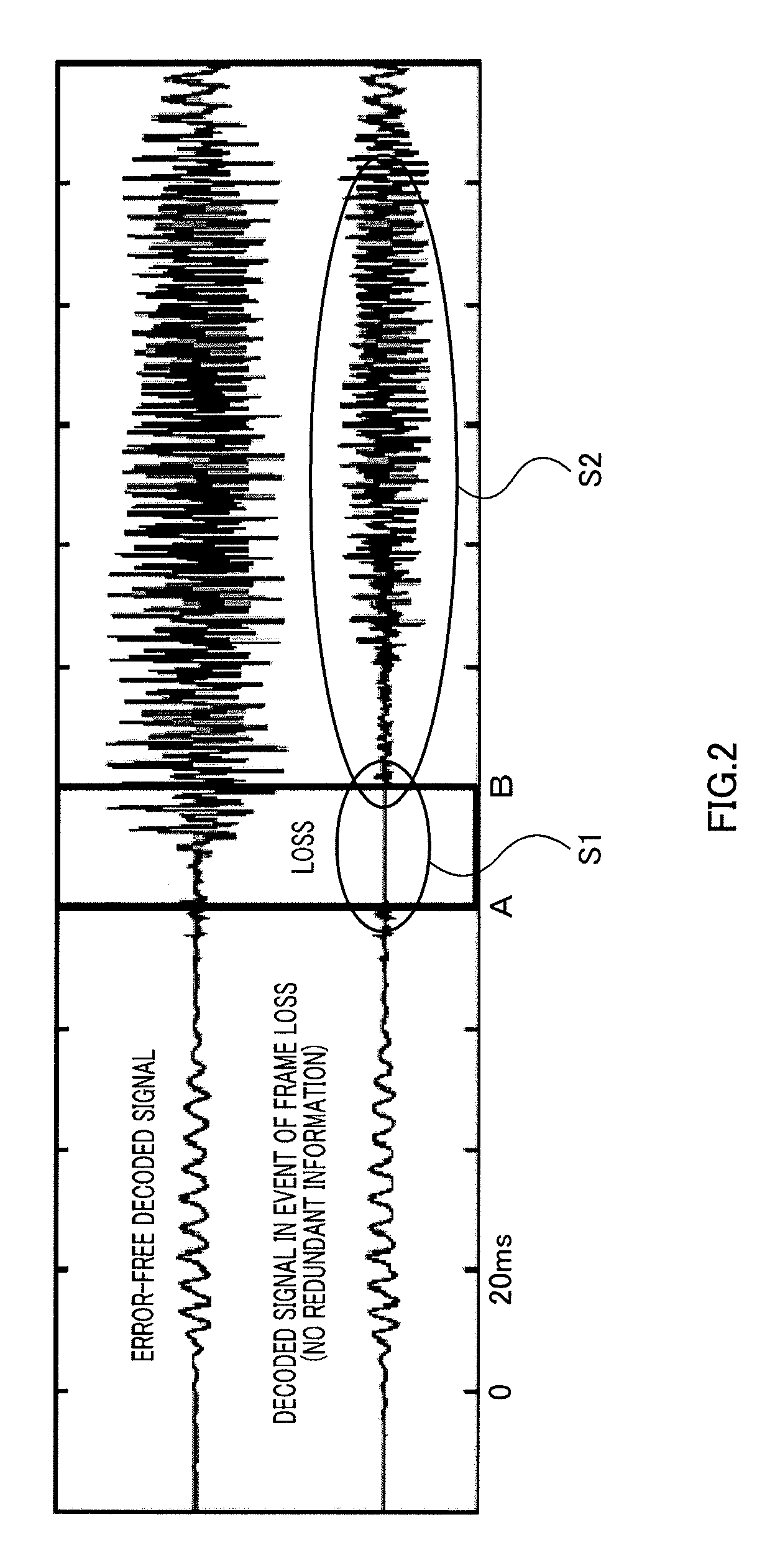
One reason for this is that signal of an onset frame changes rapidly and the correlation between the signal of the onset frame and the signal of the immediately preceding frame becomes low, and therefore concealment processing using immediately preceding frame information does not work well.
Another possible reason is that in a frame of a subsequent voiced section, an excitation signal encoded in the onset section is highly utilized as an adaptive codebook, and therefore the error of the erased onset section persists in subsequent voiced frames, tending to cause marked distortion of a decoded speech signal.

Method used


Image

  • Lost frame compensating method, audio encoding apparatus and audio decoding apparatus
  • Lost frame compensating method, audio encoding apparatus and audio decoding apparatus
  • Lost frame compensating method, audio encoding apparatus and audio decoding apparatus

Examples


Embodiment Construction

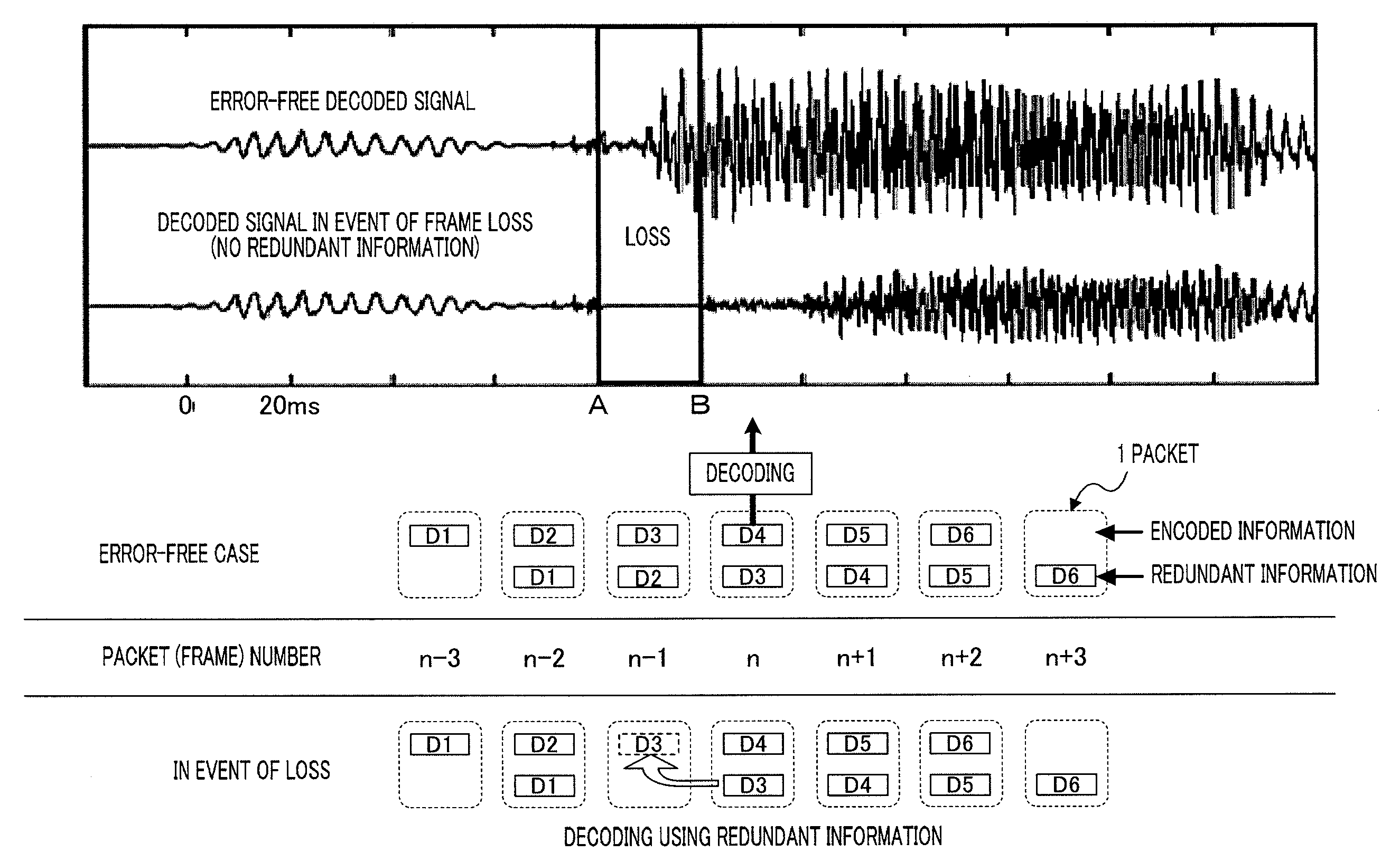
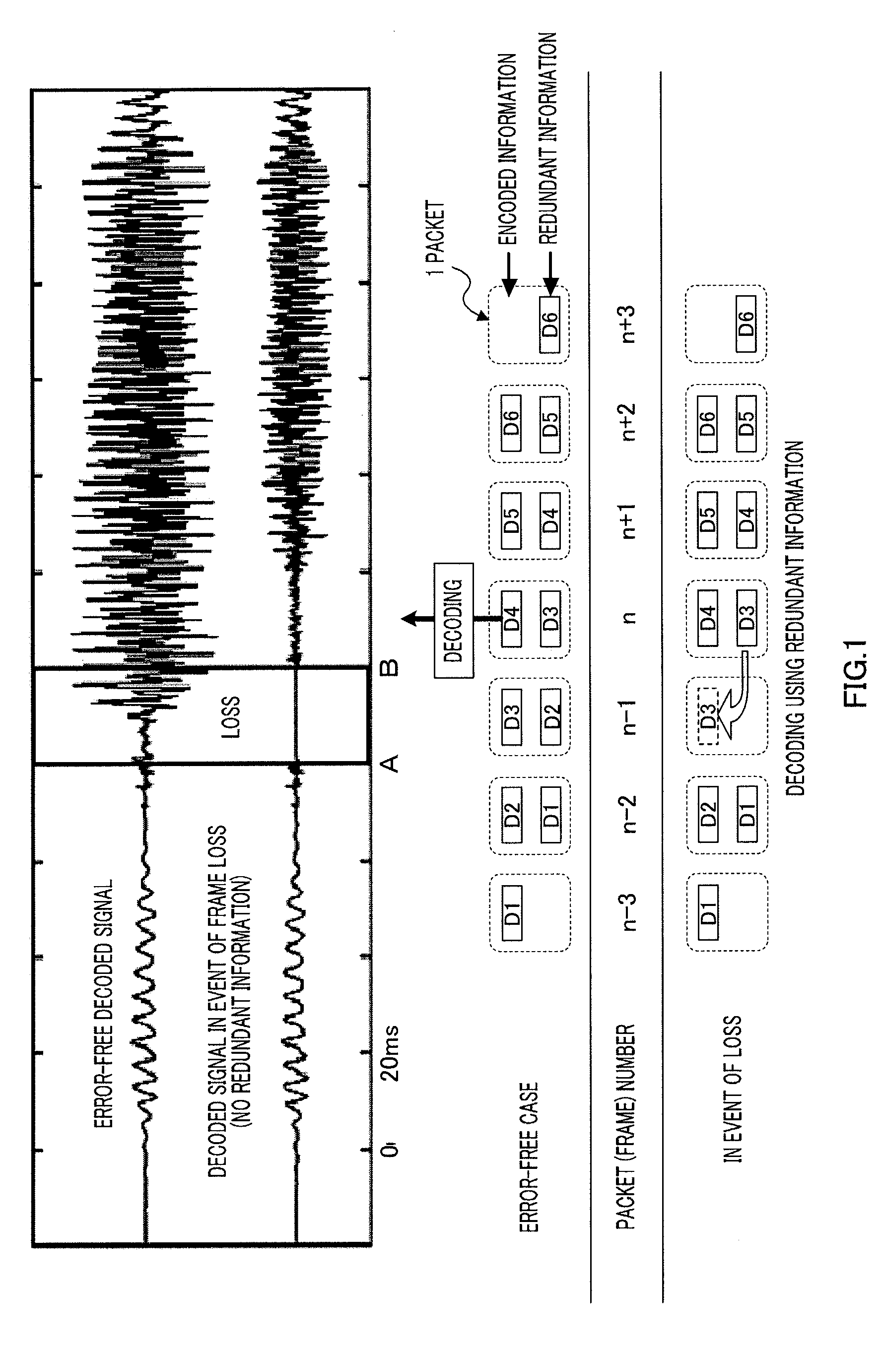
[0024]FIG. 1 is a drawing for explaining presuppositions of a frame erasure concealment method according to the present invention. Here, a case in which encoded information of the current frame (frame n in the figure) and encoded information of one frame before (frame n−1 in the figure) is packetized and transmitted in one packet is taken as an example.

[0025]By transmitting encoded information of one frame before as redundant information for concealment processing, even if the preceding packet is lost it is possible to decode a speech signal without any influence of the packet loss by decoding information of the preceding frame stored in the current packet. However, since preceding frame encoded information that should have been received in the preceding packet must be extracted after receiving the current packet, a one-frame delay occurs on the decoder side.

[0026]The present invention proposes an efficient frame erasure concealment method and redundant information encoding method i...


PUM


Abstract

A frame loss compensating method wherein even when audio codec, which utilizes past sound source information of adaptive codebook or the like, is used as a main layer, the degradation in quality of the decoded audio of a lost frame and following frames is small. In this method, it is assumed that a pitch period ‘T’ and a pitch gain ‘g’ have been obtained as encoded information of a current frame. The sound source information of a preceding frame is expressed by use of a single pulse, and a pulse position ‘b’ and a pulse amplitude ‘a’ are used as encoded information for compensation. Then, an encoded sound source signal is a vector that builds up a pulse having an amplitude ‘a’ at a position that precedes by ‘b’ from the front position of the current frame. This vector is used as the content of the adaptive codebook, so that a vector, which builds up a pulse having an amplitude (g×a) at the position of the current frame (T−b), can be used as an adaptive codebook vector at the current frame. This vector is used to synthesize a decoded signal. The pulse position ‘b’ and pulse amplitude ‘a’ are then decided such that a difference between the synthesized signal and an input signal becomes minimum.

Description

TECHNICAL FIELD[0001]The present invention relates to a frame erasure concealment method, speech encoding apparatus, and speech decoding apparatus.BACKGROUND ART[0002]A speech codec for VoIP (Voice over IP) use is required to be robust against packet loss. It is desirable for a next-generation VoIP codec to achieve error-free quality even at a relatively high frame erasure rate (for example, 6%) (however, transmission of redundant information for concealing errors of erasure is assumed to be used).[0003]In the case of CELP (Code Excited Linear Prediction) speech codecs, frame erasure in a speech onset has a large impact on speech quality in many cases. One reason for this is that signal of an onset frame changes rapidly and the correlation between the signal of the onset frame and the signal of the immediately preceding frame becomes low, and therefore concealment processing using immediately preceding frame information does not work well. Another possible reason is that in a frame ...

Claims


Application Information

Patent Timeline
IPC IPC(8): G10L19/04G10L19/00G10L19/005G10L19/09
CPCG10L19/005
Inventor EHARA, HIROYUKIYOSHIDA, KOJI
Owner PANASONIC CORP
Learn More