Thermal converter devices, systems and control methods

a technology of thermal converters and converters, applied in the direction of engines, mechanical equipment, machines/engines, etc., can solve the problems that diesel engines cannot use catalytic converters to eliminate some or all, and the current technology does not efficiently and accurately address the problems associated with diesel engine emissions, so as to reduce nitric oxide in the exhaust, efficiently reduce and/or eliminate harmful pollutants, the effect of efficient and accurate address

Inactive Publication Date: 2009-10-08
UNIVERSAL CLEANAIR TECH
View PDF0 Cites 14 Cited by
  • Summary
  • Abstract
  • Description
  • Claims
  • Application Information

AI Technical Summary

Benefits of technology

[0013]In engine applications, including but not limited to those of trucks, construction equipment, stationary generators, railroad locomotives, and marine vessels, exhaust emissions can consist of harmful pollutants such as nitric oxides (NOx), PM, CO, and HC. As described above, diesel engines cannot use catalytic converters to eliminate some or all of these pollutants, and current technology does not efficiently and accurately address the problems associated with emissions in such engines. In particular, current technology does provide for an efficient way to convert and / or burn PM, CO, and HC to carbon dioxide and water, while at the same time reducing nitric oxides in the exhaust. Therefore, an aspect of at least one of the embodiments disclosed here includes the realization that it would be advantageous to have a single system, capable of use with new engines or of retrofitting on old engines, including but not limited to diesel engines, which can efficiently reduce and / or eliminate the harmful pollutants described above.

Problems solved by technology

As described above, diesel engines cannot use catalytic converters to eliminate some or all of these pollutants, and current technology does not efficiently and accurately address the problems associated with emissions in such engines.

Method used


Image

  • Thermal converter devices, systems and control methods
  • Thermal converter devices, systems and control methods
  • Thermal converter devices, systems and control methods

Examples


Embodiment Construction

Thermal Converter System

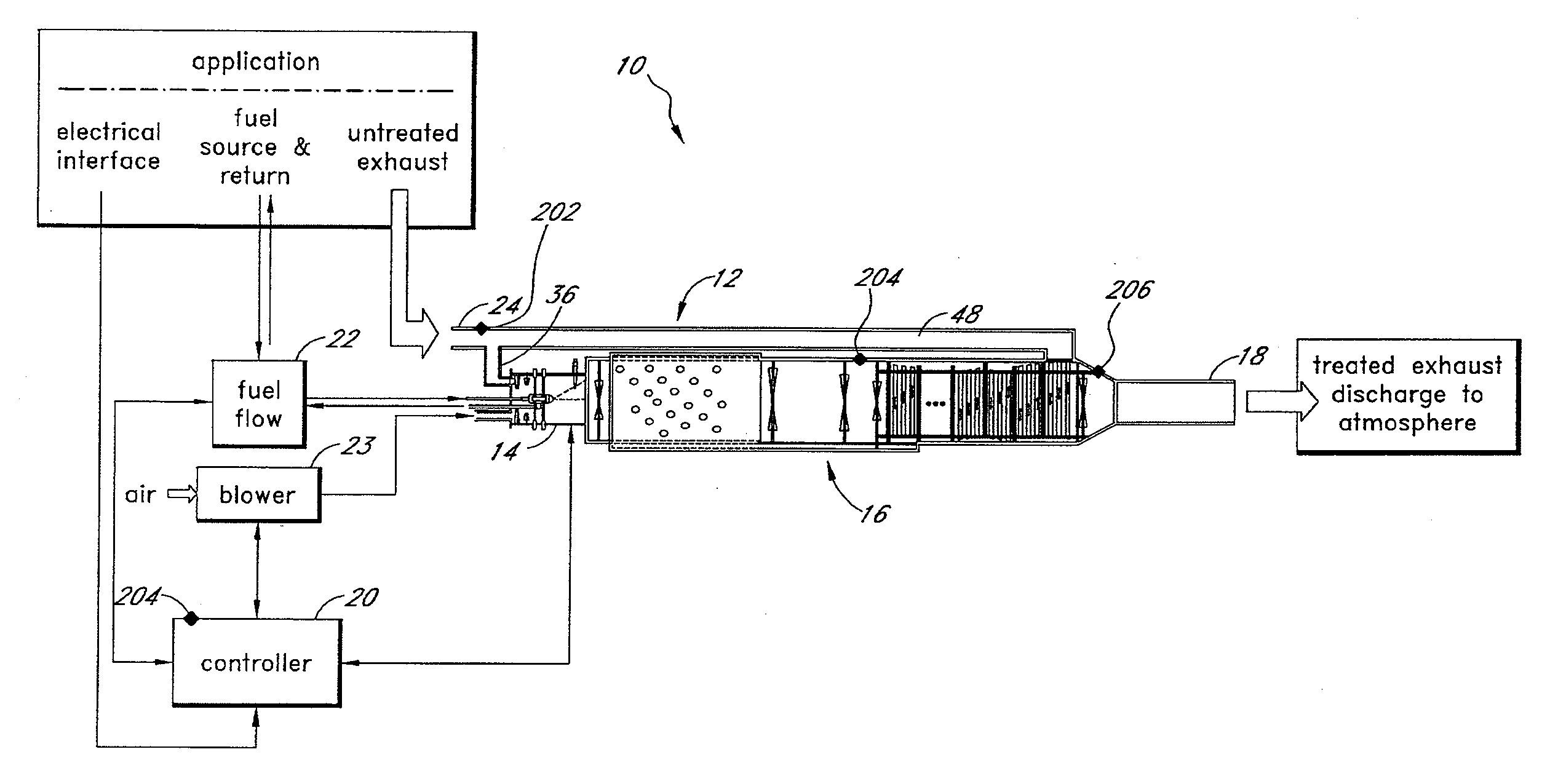
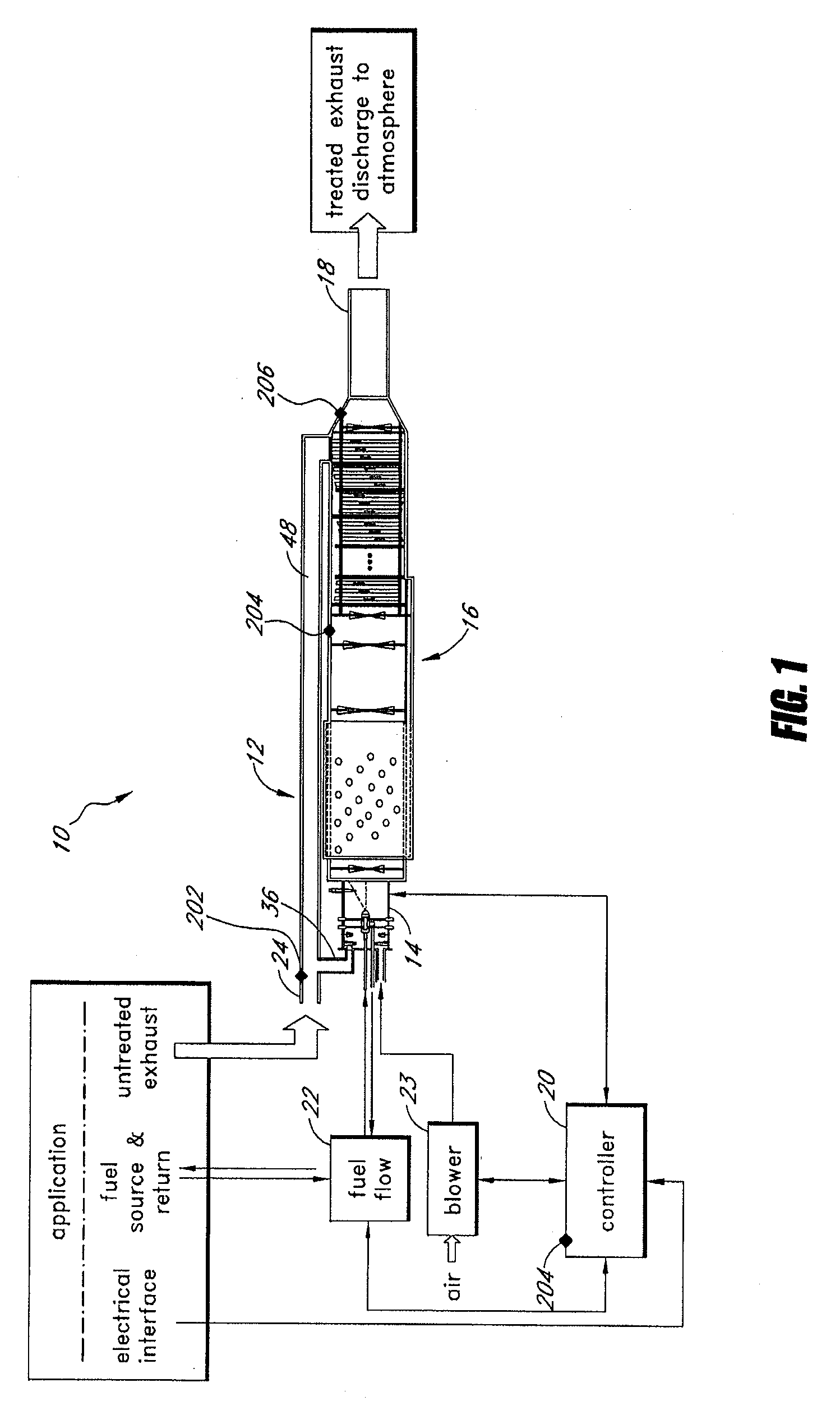
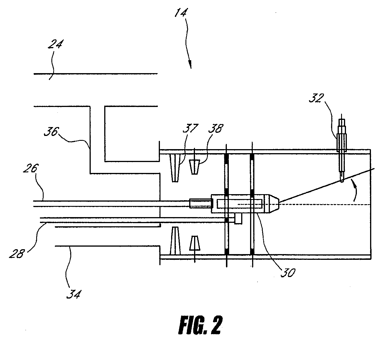
[0033]With reference to FIG. 1, an embodiment of a thermal converter system 10 can include a tube assembly 12. The tube assembly 12 can comprise an injector head 14, an assembly 16 of connected chambers and / or passageways, and an exhaust pipe 18. The tube assembly 12 can further comprise insulation material, an outer shell, and / or mounting hardware, which are not shown. In some embodiments, the tube assembly 12, or parts of the tube assembly 12, can comprise a right-circular long metal tube.

[0034]The system 10 can further include a thermal controller 20, fuel device 22, and air device 23, each of which can be in communication with and / or connected to the tube assembly 12. In some embodiments, the fuel device 22 can comprise a fuel flow rate controller. In some embodiments, the air device 23 can comprise an air blower or blowers. The system 10 described herein can be used, for example, to treat untreated exhaust gas which exits from an engine, and to reduce em...


PUM


Abstract

A system is provided for reducing exhaust emissions. The system can comprise a series of chambers, an injector head, and a controller. The controller can maintain desired temperature zones and chemical environments inside the series of chambers, and the chambers and structures inside the system 10 can provide a desired travel path for the air, fuel, and untreated exhaust mixture inside.

Description

RELATED APPLICATIONS[0001]This application claims benefit under 35 U.S.C. § 119(e) to U.S. Provisional Patent Application No. 61 / 042,665, filed Apr. 4, 2008, which is incorporated in its entirety by reference herein.BACKGROUND OF THE INVENTIONS[0002]1. Field of the Inventions[0003]The present application relates to emission reduction devices, systems, and control methods, and more particularly to devices, systems, and control methods for reducing exhaust emissions from a diesel engine.[0004]2. Background of the Inventions[0005]The toxic release into the atmosphere of exhaust emissions from compression ignition (“diesel”) engines is a global environmental problem and is prevalent in populated areas world-wide. Exhaust emission reduction of gases, solids, and condensates of diesel-powered systems have been the subject of both new and retrofit devices and methods.[0006]An internal combustion engine burns hydrocarbon fuel (approximately 85% carbon and 15% hydrogen) in oxygen from incomi...

Claims


Application Information

Patent Timeline
Patent Type & Authority Applications(United States)
IPC IPC(8): F01N3/18F01N3/26
CPCF01N3/26F01N3/30Y02T10/20F01N2610/03F01N3/36Y02T10/12
Inventor FLANAGAN, RICHARD A.HOSILYK, ROD E.ARLT, ROBISAAC, KAKKATTUKUZHY M.LOVING, RONALD E.GORDON, DAVID ALAN
Owner UNIVERSAL CLEANAIR TECH
Why Eureka
Try Eureka