Solar cell

a solar cell and carbon nanotube technology, applied in the field of solar cells, can solve the problems of increasing the cost of solar cells, consuming a large amount of electric energy, and single crystal silicon manufacturing technology that cannot meet the demand for solar cells,

Inactive Publication Date: 2009-10-08
TSINGHUA UNIV +1
View PDF19 Cites 12 Cited by
  • Summary
  • Abstract
  • Description
  • Claims
  • Application Information

AI Technical Summary

Problems solved by technology

However, the manufacturing technology of single crystal silicon doesn't satisfy the demand for the development of solar cells.
Furthermore, the manufacturing of solar cells consumes a large amount of electric energy.
As a result, the cost of the solar cell is increased and the environment is further cont

Method used


Image

  • Solar cell
  • Solar cell
  • Solar cell

Examples


Embodiment Construction

[0017]References will now be made to the drawings to describe, in detail, embodiments of the solar cell.

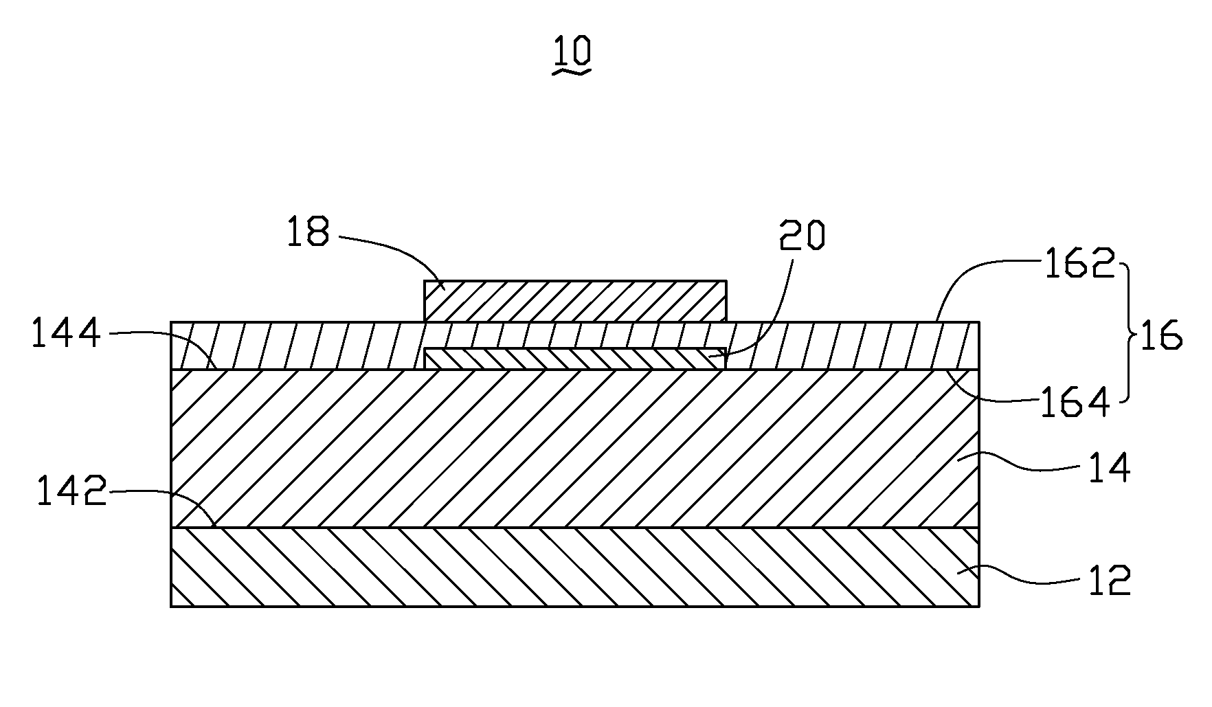
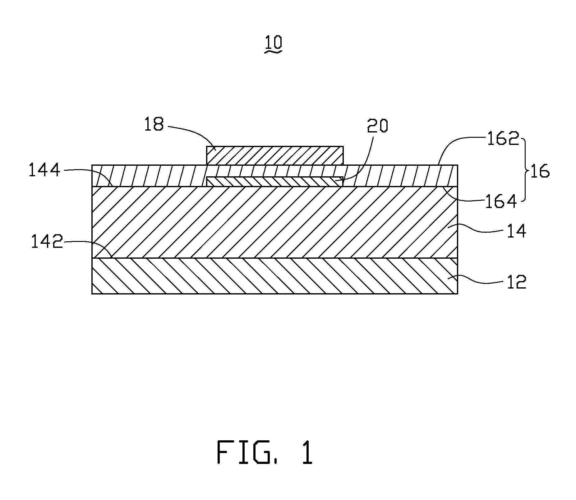
[0018]Referring to FIG. 1 and FIG. 3, a solar cell 10 includes a back electrode 12, a single crystal silicon substrate 14 and a carbon nanotube structure 16. The single crystal silicon substrate 14 includes a lower surface 142 and an upper surface 144. The back electrode 12 is located on and electrically connected to the lower surface 142 of the single crystal silicon substrate 14. The carbon nanotube structure 16 is located on and connected to the upper surface 144 of the single crystal silicon substrate 14. The carbon nanotube structure 16 includes an upper surface 162 and a lower surface 164.

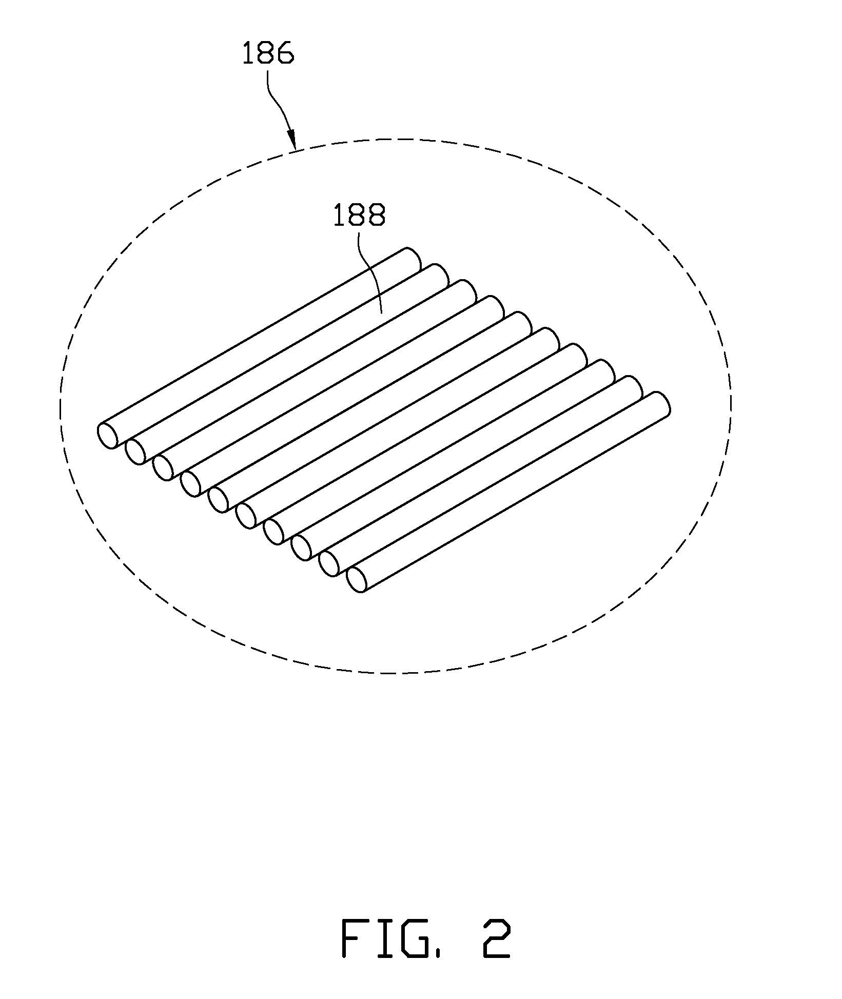
[0019]The solar cell 10 can further include at least one electrode 18. The electrode 18 can be made of silver, gold, or carbon nanotubes. A shape and a thickness of the electrode 18 can be set as desired. The electrode 18 can be located on and connected to the upper surface 162 or the lower...


PUM


Abstract

A solar cell includes a back electrode, a single crystal silicon substrate, and a carbon nanotube structure. The single crystal silicon substrate includes an upper surface and a lower surface. The back electrode is located on and electrically connected to the lower surface of the single crystal silicon substrate. The carbon nanotube structure is located on and connected to the upper surface of the single crystal silicon substrate. The carbon nanotube structure includes an upper surface and a lower surface.

Description

[0001]This application is related to commonly-assigned applications entitled, “SOLAR CELL”, filed ______ (Atty. Docket No. US18561); “SOLAR CELL”, filed ______ (Atty. Docket No. US18563); “SOLAR CELL”, filed ______ (Atty. Docket No. US18564); “SOLAR CELL”, filed ______ (Atty. Docket No. US18565); and “SOLAR CELL”, filed ______ (Atty. Docket No. US18566). The disclosures of the above-identified applications are incorporated herein by reference.BACKGROUND[0002]1. Field of the Invention[0003]The present invention relates to solar cells and, particularly, to a carbon nanotube film based solar cell.[0004]2. Discussion of Related Art[0005]Solar cells can be classified as source materials, such as silicon-based (single crystal, poly-crystalline and amorphous) solar cells and compound semiconductor-based solar cells. Among others, solar cells using single crystal silicon substrates are most widely fabricated by virtue of their excellent efficiency in energy conversion and low production cos...

Claims


Application Information

Patent Timeline
IPC IPC(8): H01L31/00
CPCH01L31/028H01L31/0352Y02E10/547H01L31/06H01L31/0745H01L31/0384
Inventor SUN, HAI-LINJIANG, KAI-LILI, QUN-QINGFAN, SHOU-SHAN
Owner TSINGHUA UNIV
Why Eureka
Try Eureka