Method of Drilling and Production Hydrocarbons from Subsurface Formations

a technology of subsurface formations and hydrocarbons, which is applied in the direction of instruments, borehole/well accessories, surveys, etc., can solve the problems of inefficiency of both wells, inability to confirm that the comparison well was drilled in an efficient manner, and high cost and time consumption of drilling operations, so as to increase the drilling rate and increase the drilling rate

Active Publication Date: 2009-10-08
EXXONMOBIL UPSTREAM RES CO
View PDF26 Cites 107 Cited by
  • Summary
  • Abstract
  • Description
  • Claims
  • Application Information

AI Technical Summary

Benefits of technology

[0011]In a third alternative embodiment, a still another method for producing hydrocarbons is described. The method includes monitoring mechanical specific energy (MSE) data along with vibration data in real-time during drilling operations. The MSE data and the vibration data are compared with previously generated MSE data and vibration data to determine at least one of a plurality of factors that limit a drilling rate. Then, drilling operations are adjusted based on the comparison to increase the drilling rate.
[0012]In a fourth alternative embodiment, yet another method for producing hydrocarbons is described. The method comprises (a) obtaining mechanical specific energy (MSE) data along with other measured data for the well concurrently with the drilling of the well, analyzing the MSE data and other measured data to determine one of a plurality of limiters that restrict a drilling rate, and (c) adjusting

Problems solved by technology

Generally, the drilling operations can be an expensive and time consuming process.
However, this approach is not able to confirm that the comparison well was drilled in an efficient manner.
Indeed, both wells may be drilled in an inefficient manner,

Method used


Image

  • Method of Drilling and Production Hydrocarbons from Subsurface Formations
  • Method of Drilling and Production Hydrocarbons from Subsurface Formations
  • Method of Drilling and Production Hydrocarbons from Subsurface Formations

Examples


Embodiment Construction

[0023]In the following detailed description, the specific embodiments of the present invention will be described in connection with its preferred embodiments. However, to the extent that the following description is specific to a particular embodiment or a particular use of the present techniques, this is intended to be illustrative only and merely provides a concise description of the exemplary embodiments. Accordingly, the invention is not limited to the specific embodiments described below, but rather, the invention includes all alternatives, modifications, and equivalents falling within the true scope of the appended claims.

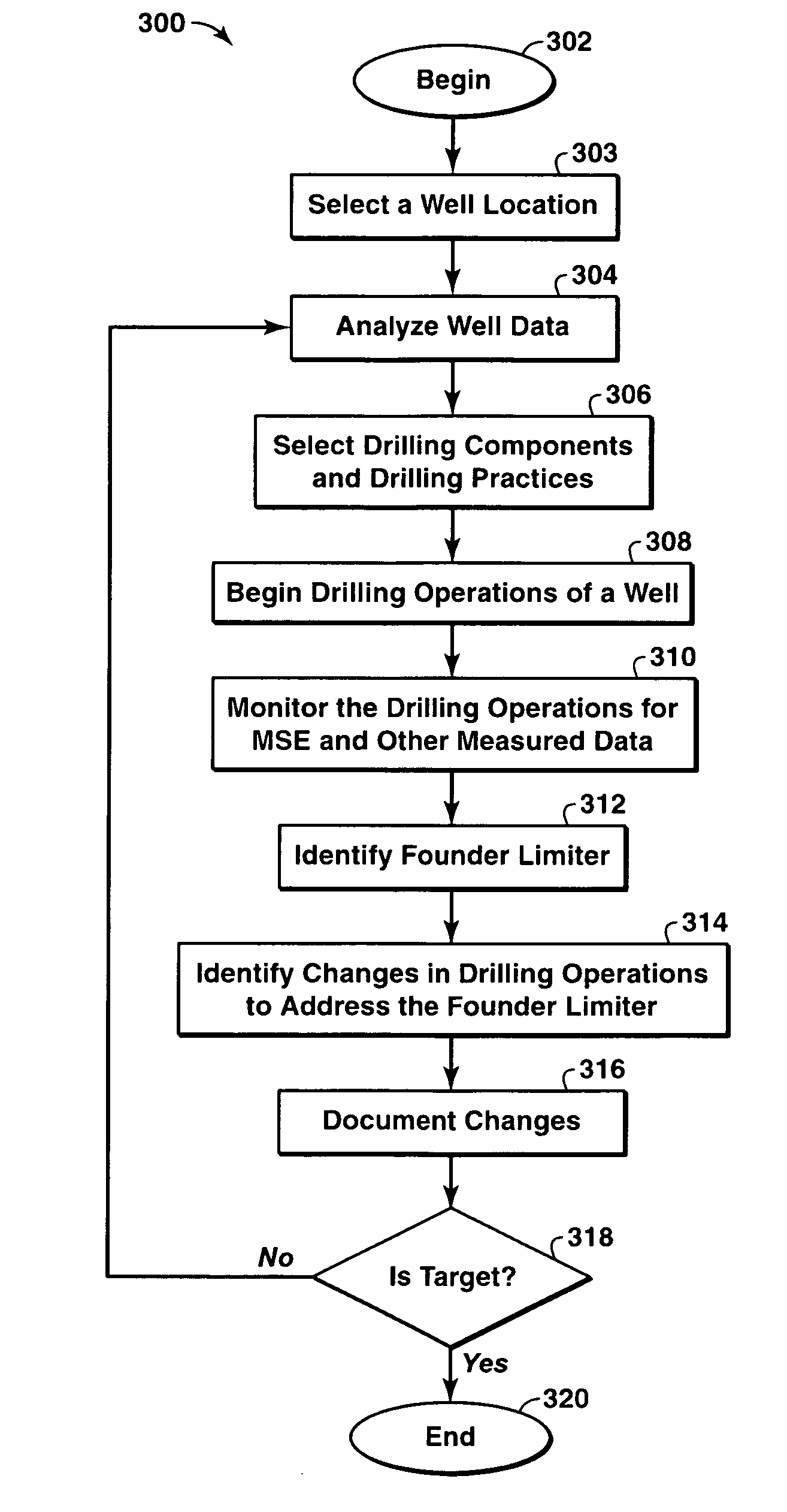
[0024]The present technique is directed to a method of improving drilling rates based on mechanical specific energy (MSE) and other measured data. In particular, estimating a drill rate, then conducting real-time analysis of MSE and other measured data, such as vibration data, may be utilized to select drilling parameters, such as weight on bit (WOB), revolut...


PUM


Abstract

A method associated with the production of hydrocarbons. In one embodiment, a method for drilling a well is described. The method includes identifying a field having hydrocarbons. Then, one or more wells are drilled to a subsurface location in the field to provide fluid flow paths for hydrocarbons to a production facility. The drilling is performed by (i) estimating a drill rate for one of the wells; (ii) determining a difference between the estimated drill rate and an actual drill rate; (iii) obtaining mechanical specific energy (MSE) data and other measured data during the drilling of the one of the wells; (iv) using the obtained MSE data and other measured data to determine one of a plurality of limiters that limit the drill rate; (v) adjusting drilling operations to mitigate one of the plurality of limiters; (vi) and iteratively repeating steps (i)-(v) until the subsurface formation has been reached by the drilling operations.

Description

CROSS REFERENCE TO RELATED APPLICATIONS[0001]This application is the National Stage of International Application No. PCT / US06 / 39345, filed 5 Oct. 2006 and claims the benefit of U.S. Provisional Application No. 60 / 738,146, filed 18 Nov. 2005 and the benefit of U.S. Provisional Application No. 60 / 817,234, filed 28 Jun. 2006.BACKGROUND[0002]This section is intended to introduce the reader to various aspects of art, which may be associated with exemplary embodiments of the present techniques, which are described and / or claimed below. This discussion is believed to be helpful in providing the reader with information to facilitate a better understanding of particular aspects of the present techniques. Accordingly, it should be understood that these statements are to be read in this light, and not necessarily as admissions of prior art.[0003]The production of hydrocarbons, such as oil and gas, has been performed for numerous years. To produce these hydrocarbons, one or more wells in a fiel...

Claims


Application Information

Patent Timeline
IPC IPC(8): E21B47/00E21B7/00G06F19/00
CPCE21B7/00E21B49/00E21B45/00E21B44/00
Inventor DUPRIEST, FRED E.
Owner EXXONMOBIL UPSTREAM RES CO
Why Eureka
Try Eureka