Method of damping tower vibrations of a wind turbine and control system for wind turbines

a technology of wind turbine and control system, which is applied in the control of electric generators, machines/engines, mechanical equipment, etc., can solve the problem of difficult and difficult to damp the very slow tower frequency, and achieve the effect of rapid damping of the oscillation of the rotor speed and easy processing

Inactive Publication Date: 2009-10-08
SIEMENS AG
View PDF10 Cites 43 Cited by
  • Summary
  • Abstract
  • Description
  • Claims
  • Application Information

AI Technical Summary

Benefits of technology

[0013]The tower velocity value may, for example, be calculated from an inclination value representing the inclination of the tower caused by the tower vibrations. Differentiating the inclination value easily leads to the tower velocity value. This inclination may for example be measured in the nacelle or at the nacelle of the wind turbine.
[0027]In this special implementation, the modification unit may further comprise an adder which is connected to the speed reference input for receiving the speed reference signal and designed to add the tower velocity signal to the speed reference input for establishing the modified speed reference signal. Hence, the modified speed reference signal is the sum of the speed reference signal and the tower velocity signal. Since the tower velocity is oscillating due to the vibrations this sum represents an oscillating speed reference for the pitch controller. By use of this oscillating speed reference the difference between the (oscillating) actual rotor speed and the oscillating speed reference can be reduced in a control process. By this measure it becomes possible to rapidly damp oscillations in the rotor speed.

Problems solved by technology

This allows for damping very slow tower frequencies which is not easily possible with the state of the art.

Method used


Image

  • Method of damping tower vibrations of a wind turbine and control system for wind turbines
  • Method of damping tower vibrations of a wind turbine and control system for wind turbines
  • Method of damping tower vibrations of a wind turbine and control system for wind turbines

Examples


Embodiment Construction

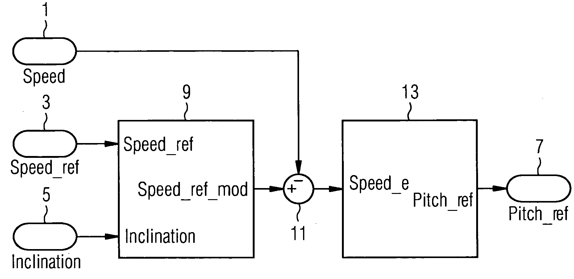
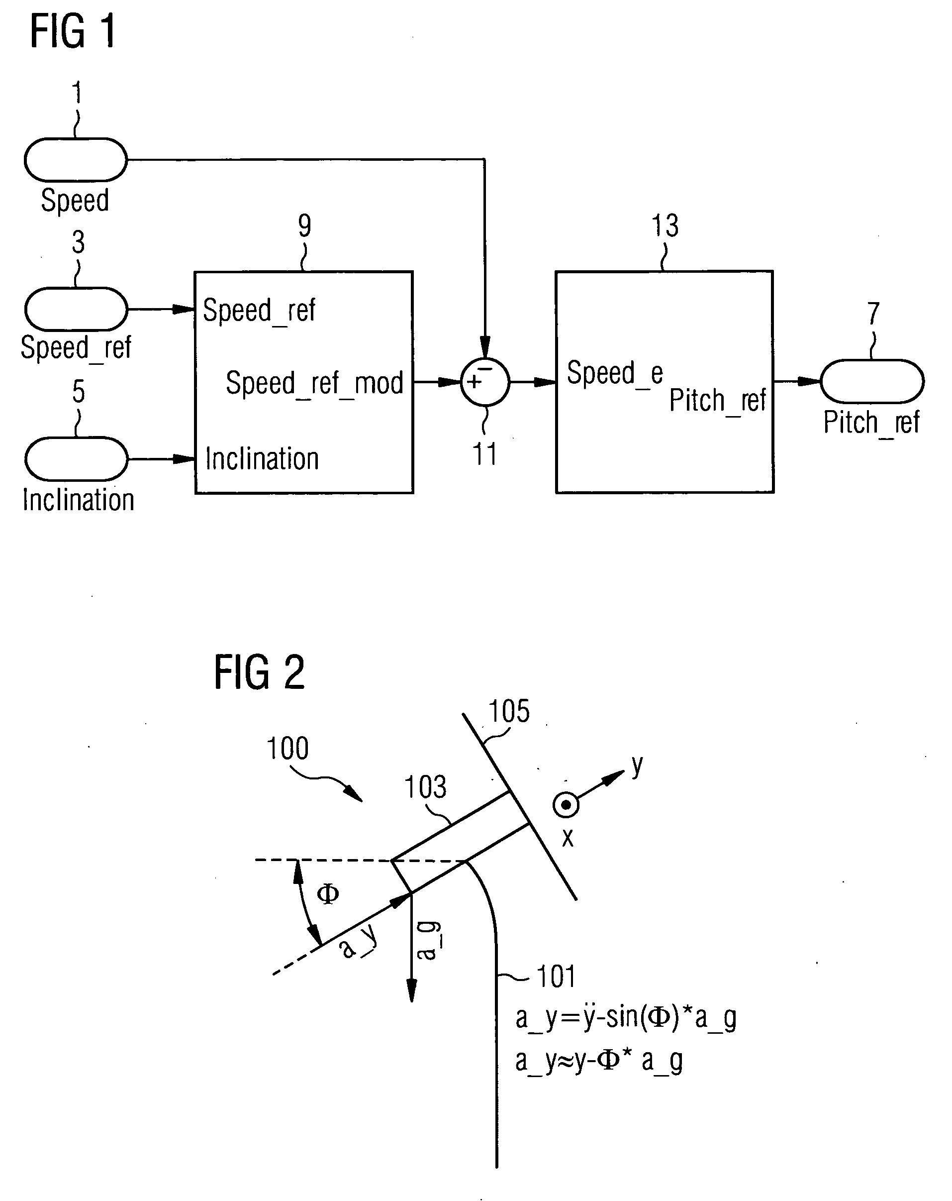
[0040]An embodiment of the inventive control system is shown in FIG. 1. The system is to be used in a wind turbine which is equipped with rotor blades and a pitch actuator system. It comprises three inputs, namely a rotor speed input 1 which is designed for receiving a rotor speed signal representing the actual rotor speed value of the wind turbine's rotor, a speed reference input 3 which is designed for receiving a speed reference signal representing a speed reference value for the rotor speed, and an inclination signal input 5 which is designed for receiving a signal representing an inclination of the tower. The control system further comprises a pitch reference output 7 which is designed to output a pitch reference signal to the pitch actuator system of the wind turbine. The pitch reference signal represents the pitch values to be set by the pitch actuator system.

[0041]A modification unit 9 is connected to the speed reference input 3 for receiving the speed reference signal and t...


PUM


Abstract

A control system for a wind turbine is provided. A pitch-control unit establishes a pitch-reference signal representing a pitch to be set by the pitch-actuator system. A rotor-speed input receives a signal representing a speed of the rotor. A speed-reference input receives a speed-reference signal for the rotor speed. An inclination-signal input receives a signal representing a tower inclination. A pitch-reference output outputs the pitch reference signal. A modification unit is connected to the speed-reference input to receive the speed-reference signal and connected to the inclination-signal input to receive the inclination signal. The modification unit establishes a modification signal based on the inclination signal, to modify the speed-reference signal via the modification signal, and to output a modified-speed-reference signal. The pitch-control unit connected to the modification unit to receive the modified-speed-reference signal and establish the pitch-reference value at least based on the difference between the modified-speed-reference and the rotor-speed signals.

Description

CROSS REFERENCE TO RELATED APPLICATIONS[0001]This application claims priority of European Patent Office application No. 08006746.5 EP filed Apr. 2, 2008, which is incorporated by reference herein in its entirety.FIELD OF INVENTION[0002]The present invention relates to a method of damping tower vibrations of a wind turbine which is equipped with rotor blades, a pitch controller, and a pitch actuator system, in which the tower vibrations are damped by setting the pitch of the rotor blades. In addition, the present invention relates to a control system for use in a wind turbine which is equipped with rotor blades and a pitch actuator system.BACKGROUND OF INVENTION[0003]In wind turbines, tower vibrations will be excited by wind conditions in the wind field acting on the wind turbine. In land based wind turbines these tower vibrations are of high frequency and produce only small tower inclinations. However, e.g. wind turbines mounted on floating foundations of the so-called spar-buoy typ...

Claims


Application Information

Patent Timeline
Patent Type & Authority Applications(United States)
IPC IPC(8): H02P9/04
CPCF03D7/0224F03D7/0276F03D7/0296F03D7/043F05B2260/80Y02E10/723F05B2270/327F05B2270/334F05B2270/706F05B2270/802F05B2270/807F05B2260/96Y02E10/72
Inventor EGEDAL, PER
Owner SIEMENS AG
Why Eureka
Try Eureka